Each arm in a robot has usually 3 joints, with two
perpendicular axes allowing two independent rotations,
corresponding to two degrees of freedom. Thus, there are 6
degrees of freedom for each arm, enough to be able to reach
any point, in any desired direction, within its maximum
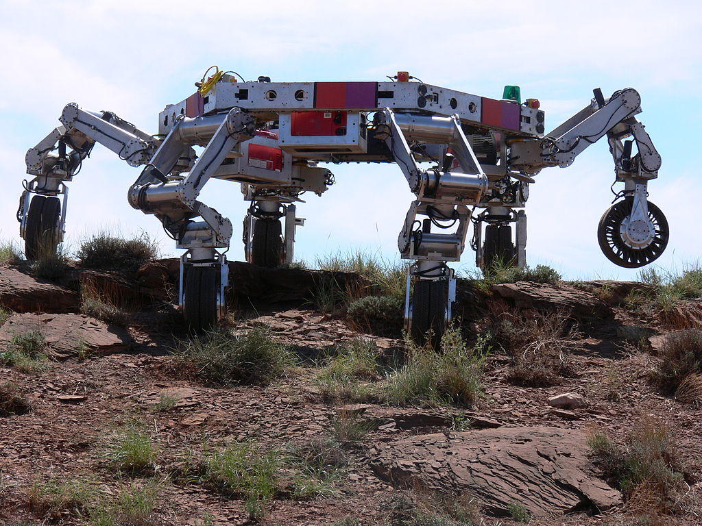
range. The ATHLETE ( All-Terrain Hex-Legged
Extra-Terrestrial Explorer ) robot, used by NASA
for lunar exploration, has six 3-joint arms which means 36
degrees of freedom. Plus the 3 degrees of freedom to
determine the position of a point in the body of the robot,
that makes a total of 39 degrees of freedom. The human arm,
not including the hand, has 7 degrees of freedom
corresponding to three independent rotations at the
shoulder, two rotations at the elbow and two other rotations
at the wrist.
8.1. Degrees of freedom and phase space
All mechanical systems considered in the previous chapter
have a single degree of freedom (a coordinate or an angle
which determines the position) and two state variables: one
variable for the position and its derivative with respect to
time (linear or angular velocity).
The state of a system with
degrees of freedom is
specified by
independent variables dependent on time,
called generalized coordinates, which
we will denoted by the letters:
,
, …,
. These variables can be distances, angles or any other
quantities. The time derivatives of each of these variables
are the generalized velocities:
.
The phase space of the system has
dimensions. The
coordinates of a point in phase space are (
,
…,
,
, …,
) and the
components of the phase velocity are (
,
…,
,
, …,
). To determine the expression of the phase
velocity at any point in phase space, it is necessary to
know
expressions for the generalized accelerations
, in terms of the generalized coordinates and
velocities, which are
called equations of motion.
The equations of motion can be derived from Newton's second
law. However, it would be necessary to relate each
generalized acceleration
to the acceleration of
the center of mass of a component of the system and identify
all external forces acting on that component. Some of those
forces are forces of constraint, for example, the tension on a
string or the normal force on a surface. As it was discussed
in the previous chapter, the evolution equations can also be
obtained from the derivatives of the hamiltonian
function. The problem is that in more complicated systems
than those considered in the previous chapter, the
hamiltonian is not the mechanical energy per unit mass or
moment of inertia, but it might be a more complicated
expression. This chapter introduces a more general method to
derive the equations of motion without the need to identify
any forces of constraint.
8.2. Lagrange equations
The total kinetic energy
of a mechanical
system is equal to the sum of all the kinetic energies of
translation and rotation of its parts. In general, it is a
function that can depend on all the generalized coordinates
and velocities and time:
(8)
The motion of a system is usually not completely free, but
subject to some constraints; there are forces of constraint
resulting from those constraints. For example, in a car moving
on a road, the normal force exerted by the road on the tires
is the force of constraint that ensures that the trajectory of
the car stays over the surface of the road. The static
friction on a wheel with traction is also a force of constraint,
which ensures that the wheel rotates without sliding on the
surface. The fact that the car remains in contact with the
road surface as it moves and the friction on the tires
prevents them from moving sideways, reduces the three
coordinates of position to a single degree of freedom: the
displacement along the road. When the wheels rotate without
skidding, the angular velocity of the wheels depends on the
speed of the car on the road. That dependence also implies a
dependence between the angle of rotation of the wheels and
the displacement of the car along the road; thus, only one
of those two variables is enough to describe the motion of
the car and the rotation of the wheels.
Each constraint on a system's motion reduces its number of
degrees of freedom. A constraint that can be written as an
equation depending on the generalized coordinates of the
system is called holonomic. When a system
is holonomic, namely all constraints to
its motion are holonomic, Newton's second law leads to the
following equations (the proof is given
in Appendix B ):
(8.2)
where
is the
component of
the generalized force, defined
as:
(8.3)
where all forces
(internal or external) are
summed and
is the position of the point force is
applied. However, some of the forces do not
contribute to the generalized force
. For example,
normal forces and static friction can be neglected because
they are applied in a fixed point
and therefore,
. The tension in a
string with constant length can also be ignored because it
acts in opposite directions at both ends of the string and the
sum of
at both ends
gives zero.
Among the forces to be included in
, some may be
conservative and, in these cases,
, where
is the potential energy associated to that force. Thus,
the contribution of that conservative force to
equals
and
equations 8.2 can be written
as
(8.4)
where
is the total potential energy of the system and
the components
of the generalized force include only
non-conservative
forces. Equations 8.4 are
called Lagrange equations, valid for
holonomic systems. In the particular case of conservative
systems, the right sides of the equations are zero.
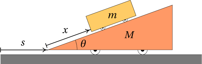
Example 8.1
The cart in the figure, with mass
, can move freely on
the surface of an incline with mass
. The incline has
wheels that let it move freely on the horizontal
table. Assuming that the mass of the wheels is much
smaller than
and
and that the friction in the axes
of the wheels are negligible, find the equations of motion
of the system.
Resolution. To determine the positions of the cart
and the incline at any instant, we need to know position of
of some point of the inclined, on the horizontal table
and the position
of a point of the cart on the surface
of the incline. The figure above shows how these two
variables can be defined. Thus, the system has two degrees
of freedom and the generalized velocities are
and
.
The derivative
is also the velocity of the center
of mass of the incline. And
is the velocity of the
cart, relative to the incline. Choosing an axis
perpendicular to
and pointing upwards, the vector
expressions for the velocity of the incline and the velocity
of the cart relative to the incline are:
The velocity of the cart, relative to the table, is the sum
of those two vectors:
And the square of its module is,
The rotational kinetic energy of the wheels
is negligible, since their masses are very small. Thus,
the total kinetic energy of the system is:
The gravitational potential energy of the incline can be
ignored because it remains constant. Therefore, the
potential energy of the system is the gravitational
potential energy of the cart:
Notice that the height of the cart's center of mass of the
cart, from the surface of the table, is slightly bigger than
but the difference is a constant that also
be neglected since we only need the derivative of
.
There are no nonconservative forces (or rather, they're
effect is negligible). Thus, the right-hand sides of the
Lagrange equations 8.4 are
zero. In the first Lagrange equation, related to the
coordinate
, we must compute the following
derivatives:
And the Lagrange equation becomes,
For the coordinate
, the derivatives involved are
And the corresponding Lagrange equation is
Solving the two Lagrange equations for the accelerations
and
, we obtain the two equations of
motion:
The two accelerations are constant;
being
negative and
positive. That means that the cart
descends the incline while this moves to the right.
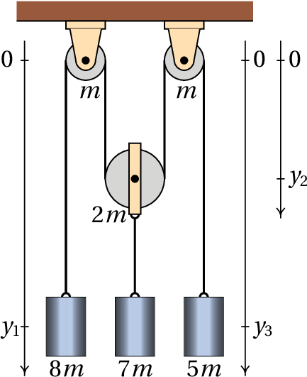
Example 8.2
In the system of pulleys and shown in the figure, the
pulley in the middle can move vertically while the other
two pulleys are fixed to the ceiling. The masses of the
two fixed pulleys are
, the mass of the moving pulley
is
and the masses of the 3 cylinders are
,
and
(
for the cylinder in the middle
already includes the mass of the support that links it to
the moving pulley). The masses of the strings and the
friction in the axes of the pulleys are negligible and the
string makes the pulleys turn without sliding over
them. Find the values of the accelerations of the 3
cylinders.
Resolution. This example will also be used to
illustrate how to use Maxima to solve Lagrangian mechanics
problems. We begin by defining the generalized variables. To
determine the vertical position of the cylinders and the
moving pulley 3 distances are required, which can be the
three variables
,
and
indicated in the
figure.
and
are the positions of some points in
the two cylinders on the left and the right and
is the
position of the moving pulley, which differs from the
position of the cylinder in the middle by just a
constant.
The constraint that the length of the string remains
constant leads to the following equation:
where
is a constant. This equation can be used to
replace
in terms of
and
. Thus, the system
has two degrees of freedom, which can chose as
and
. The two generalized speeds are
and
; the relation between
and the two
generalized speeds is obtained by differentiating the
previous equation. The result is trivial, but we will show
how it is done in Maxima, would be useful in cases more
complicates. Derivatives computed with the Maxima's
function diff are partial derivatives. To be find
the ordinary derivative of the previous equation with
respect to time, it is necessary to declare that the
derivative of
is not zero, but the velocity
and
similarly for
. As it will be necessary later, we can
also declare that the derivatives of
and
, are
the accelerations
and
. The command used in
Maxima to define the derivative of a variable is
gradef. The following commands are used
to define set
and
in terms of the degrees of
freedom and the corresponding velocities
Since the string does not slide over the pulleys, the
angular velocity of each pulley is
, where
is the velocity of the string relative to the center of the
pulley and
is the radius of the pulley. Assuming that
the disk of each pulley is a uniform cylinder, its moment of
inertia relative to its axis is
, where
is
the mass of the pulley. Thus, the total rotational kinetic
energy is
The total kinetic energy of the system is:
Where the indices 1, 2 and 3 refer to the 3 cylinders and
the 3 pulleys (from left to right), the masses
in
lowercase letters are the masses of the cylinders and the
masses
in capital letters are the pulley masses. The
velocities of the 3 cylinders are
and the velocities
of the strings, relative to the centers of the 3 pulleys are
. Notice that the pulley in the middle has both
translational and rotational kinetic energy.
The gravitational potential energy of the system, up to
some constant, is:
We now replace the values of the masses in terms of the
parameter
and write these energies in terms of the 2
degrees of freedom and the corresponding velocities
and
(notice that
,
and
).
That can be done in Maxima as follows:
It should be noted that the results do not depend on
and the three accelerations are constant. The cylinder on
the left side has acceleration equal to
,
downwards (because
is positive). The cylinder in the
middle and the moving pulley have acceleration
, upwards and the acceleration of the third
cylinder is
, upwards. If the 3 cylinders were
initially at rest, the cylinder on the left would start to
go down and the other two cylinders would go up.
8.3. Equilibrium conditions
In the two examples solved in the previous section, the
values obtained for the accelerations were constant. In more
general cases, the accelerations will be expressions that
depend on the generalized coordinates, velocities and
time. The resolution of those systems of differential
equations will be undertaken in later chapters.
Even before the equations of motion are solved, it is
possible (and convenient) to find the values of the
generalized coordinates for which the system will be in
equilibrium. The condition for kinetic equilibrium is that
the accelerations are zero and if the velocities are also
zero, the equilibrium is static.
Recall that in systems with only one degree of freedom, the
instability of the equilibrium points is determined from the
sign of the derivative of the acceleration, with respect to
the generalized coordinate. The equilibrium point is stable
when the derivative is negative or unstable when it is
positive.
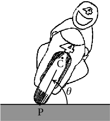
Example 8.3
A motorcyclist moving with velocity
on a curve with
radius
tilts his body and the motorcycle at an angle
, above the horizontal, towards the center of
curvature of the curve, to avoid falling to the side. Find
the value that
should have, in terms of
,
and
, which is the distance between the point of
contact of the tires with the road, P, and the center of
mass, C, of the system.
Resolution. Due to the inclination of the motorcycle, points P
and C are not at the same distance from the center of the curve. Since
the distance from point P to the center is
and the speed of point
P relative to the road is
, the distance from point C to the center
is
and the speed of point C is:
in a direction parallel to the velocity of point P. But
since the angle
can vary, point C also has another
velocity component
, in the plane
perpendicular to the velocity of P. Thus, the kinetic energy
of translation is
There are also rotational kinetic energies, associated with
the angular velocity
, the angular velocity of
the wheels on their axles and the rotation of the whole
system in the horizontal plane, since the motorcyclist
enters the curve pointing in one direction and leaves
pointing in the opposite direction. The calculation of those
energies goes beyond the goals of this introductory book; we
will consider the case in which the change in those energies
can be neglected. The gravitational potential energy of the
system is
The partial derivatives of the energies with respect to
and
are
And the equation of motion is
The height of the center of mass,
, is usually much
smaller than the radius of the curve. Thus, the expression
inside the parentheses is approximately 1 and a good
approximation is
It the system is in equilibrium,
, and the
angle should be:
(8.5)
And the derivative of the generalized acceleration with
respect to the angle is:
Which is positive because
. We conclude that
the equilibrium is unstable.
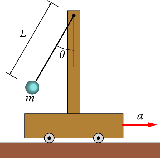
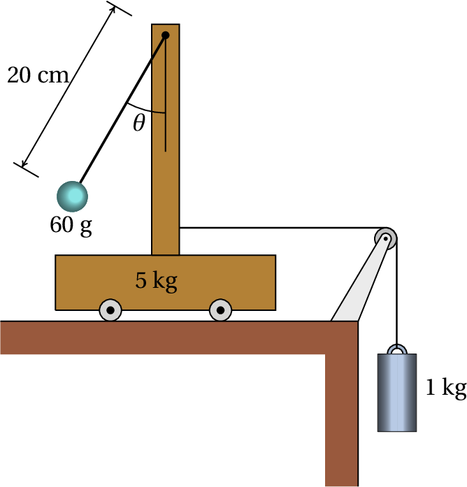
Example 8.4
A cart moves on a horizontal table with constant
acceleration
. the cart has a vertical pole with a
simple pendulum of mass
and length
. Determine the
value of the angle
at which the pendulum remains
in equilibrium with respect to the cart. Assume that the
mass of the pendulum's string is negligible and that the
radius of the sphere is much smaller than
.
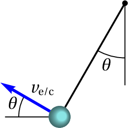
Resolution. The velocity of the cart will always be
horizontal and with value
, where
is the time from
when the cart speed was zero. The figure on the right shows
the velocity
of the ball, relative to the
cart, at an instant when
is positive. The
relative velocity
equals
and using a coordinates system with axis
in the same
direction and sense of the acceleration of the cart and
axis vertical pointing upwards, the components of vector
and the cart's velocity are:
The velocity of the sphere relative to the table is the sum
of those two vectors
In Maxima, if
is represented by the variable
and
by the variable
, the expression of
the kinetic energy of the sphere is obtained from its
velocity, considering that
We next introduce the expression of the potential energy of
the sphere , compute the derivatives of the generalized
coordinate and velocity with respect to time, introduce them
into the Laplace equation and solve it to obtain the
expression for the angular acceleration
which will be denoted by the variable
.
There will be static equilibrium when the angular velocity
and acceleration are both zero:
,
, which leads to the condition for the
angle in the equilibrium position:
(8.7)
And the derivative of the angular acceleration with respect
to the angle is
Which is negative because at the point of equilibrium
is between 0 and
. We conclude that the
equilibrium is stable. The pendulum could be swing around
the angle
at the equilibrium position.
Notice that the equation of motion depends on the
acceleration of the cart but not on its speed. A measurement
of the equilibrium position of the pendulum can be used to
find the acceleration of the cart, but not its velocity.
8.4. Dissipative Forces
In all the examples shown in previous sections there were
only conservative forces and thus the generalized force was
zero. The following examples include non-conservative
forces.
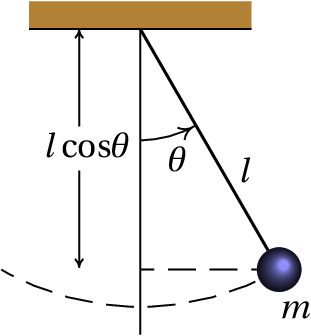
Example 8.5
A simple
pendulum is formed by a small object of mass
,
hanging from a string of length
. The string's mass
is negligible compared to
. Determine the equation of
motion, including the air resistance.
Resolution. The force of resistance of the air is
proportional to the square of the velocity of the pendulum,
and in the direction opposite to that velocity (see
equation 4.14 in
chapter 4). Since the velocity of the pendulum has value
, the expression for the air resistance
force is:
Where C is a constant. Choosing the origin at the point
where the string is attached to the support, the position
where this resistance force acts is
And its derivative with respect to
is
where
is the tangent unit vector to the
circular trajectory of the pendulum, in the sense that
increases. The generalized force is then
The kinetic and potential energies and their derivatives
are similar to the last example in the previous section,
setting
The Lagrange equation leads to
(8.8)
8.5. Forces of constraint
One of the advantages of Lagrangian mechanics compared to
vector mechanics is not having to identify the forces of
constraint, their directions and the points where they are
applied. However, in some cases we may want to find those
forces. For example, when there is kinetic friction between
two surfaces, the frictional force is proportional to the
normal force, which is a force of constraint.
There is a method that allows us to calculate the forces of
constraint from the Lagrangian equations. It begins by
identifying the constraint to which the force of constraint
is associated and writing it in the form
. In the case of
Example 8.2, the constraint that
the length of the string remains constant,
, is responsible for the appearance of the tension force
along the string and turns
dependent of
and
. Therefore, to find the tension in the string, the 3
variables (
,
,
) are assumed to be
independent generalized coordinates, thus increasing the
number of Lagrange equations to 3. A function
called Lagrange multiplier and an
additional equation,
, are
introduced. In the case of
example 8.2 the function
is
and the Lagrange multiplier represents
the tension in the string.
The next step is to add a
to each Lagrange equation,
(8.9)
where
. The following example shows how to
calculate the Lagrange multiplier. Each term
is the component of the
force of constraint acting at
. In the case of
example 8.2,
,
and
are the values of the
tension of the string at each of the 3 blocks, which are
different.
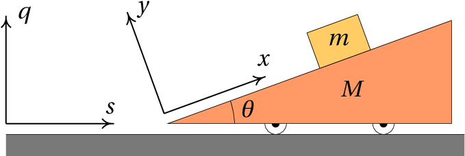
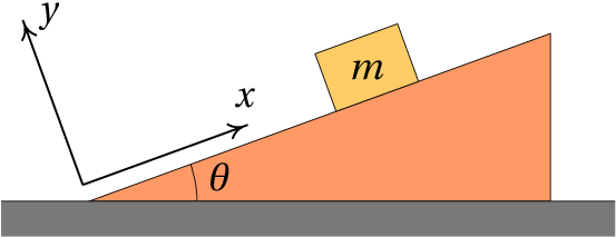
Example 8.6
A block of mass
slides over an incline of mass
which has wheels that let it move freely on a horizontal
table, as shown in the figure. The coefficient of kinetic
friction between the block and the incline is
. Assuming that the mass of the wheels is
much smaller than
and
and that the friction in the
wheel axes is negligible, find the equations of motion of
the system.
Resolution. The figure above shows the two
coordinates systems that will be used below. The axes
and
are fixed to the table while the axes
and
move with the incline.
This example is similar to
Example 8.1 , but with a
non-conservative force: kinetic friction between the block
and the incline. Since the kinetic frictional force is equal
to
, where
is the normal force
between the block and the plane, we need to find that normal
force. We then pretend that the block does not keep in
contact with the incline and that the two coordinates
and
may change. There are thus 3 degrees of freedom:
,
and
and the equation of the constraint which
causes the block to remain in contact with the inclined
plane is:
We introduce a Lagrange multiplier
and the 3
generalized components of the force of constraint are:
This shows that the force of constraint points in the direction
of axis
and the Lagrange multiplier is the normal force
itself between the block and the plane,
.
To determine the components of the velocity in terms of the
generalized velocities (
,
,
), we
will show a method different from the one that was used in
the resolution of
example 8.1. The position vector
of the center of mass of the incline is
And its derivative is the velocity vector of the incline:
.
The position of the block relative to the center of mass of
the inclined plane is
where
is the vector from the center of
mass of the incline to the origin of the frame
. The
position of the block relative to the table is
. Since the unit
vectors of frame
with respect to frame
are
Then the position of the block with respect to frame
is,
And the velocity of the block is obtained by
differentiation of this last expression
Since the kinetic energy of the wheel rotation is
negligible, the total kinetic energy of the system is:
The height of the block, relative to the table is
And, ignoring the constant terms, the gravitational potential
energy of the system is
In this case there is an internal force that performs work:
the kinetic frictional force between the block and the
incline. To calculate the components
of the
generalized force, we take into account that in
the vector
is the position of the block relative to the
incline
, because the force is
internal. Using the expression given above for
, the 3 partial derivatives are
,
and
. Since the frictional force
is
, the three components
of the generalized force are then
The Lagrange equations 8.9 for
the 3 coordinates are
These 3 equations can be solved to find the 2 equations of
motion for
and
in terms of (
,
,
,
) and the force of constraint
. To
substitute
,
and
in terms of the
generalized coordinates and velocities (
,
,
,
) we use the constraint equation,
, which in this case is
and, therefore,
. Eliminating the terms
in the
Lagrange equations and solving for
,
and
we obtain
(8.10)
where
. In the
case when kinetic friction is neglected
(
),
becomes
and the
equations of motion are the same as those obtained in
Example 8.1.
Questions
(To check your answer, click on it.)
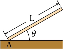
A very long and homogeneous bar of length
and mass
is falling to the ground. At point A the coefficient
of static friction is high enough to prevent point A from
moving while the angle
decreases. Find the
expression for the kinetic energy of the bar in terms
of the angular velocity
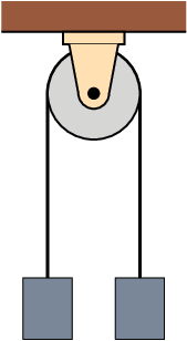
In an Atwood machine, two blocks are hung at the ends of
a string passing through a pulley, as shown in the
figure. The heavier block descends with constant
acceleration and the lighter block rises with the same
acceleration value. The masses of the blocks are
and
and the pulley is a homogeneous disk with mass
. Neglecting the friction in the pulley's shaft and
the air resistance, determine the value of the
acceleration of the blocks.
The kinetic energy of a particle moving inside a
cylinder of radius
is given by
, where
and
are the coordinates of the position of the particle in
the cylinder, and its potential energy is given by
, where
,
and
are constant. Find the expression for the acceleration
.
The expressions for the kinetic and potential energies
of a system with two degrees of freedom,
and
,
are:
and
. Find expression for the acceleration
.
The kinetic and gravitational potential energies of a
celestial body in orbit around the Sun are given by the
expressions:
where
is the
mass of the body,
its distance from the Sun,
is an angle measured on the plane of the orbit with vertex
in the Sun and the distances are to be measured in
astronomical units and the time in years. Find the
equation of motion for
Problems
In
example 8.1, if the masses are
kg and
kg and the angle is
, (a) determine the values of the
acceleration of the incline and of the cart relative to the
incline. (b) If at an initial moment the incline and
the cart are at rest, with
cm, compute the
velocity of the cart, relative to the incline, when it
reaches the base of the incline (
) and the time it
takes. (c) Find the velocity of the incline when the
cart reaches the base of the incline.
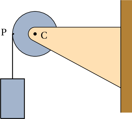
One end of a string is attached to a point
P of a pulley, the string is then winded around the pulley
and a block is hanged on the other end of the string. The
system has a single degree of freedom, which can be the
height
of the block. Assume that the pulley is a
homogeneous disk with mass equal to the mass of the block
and that the mass of the string, the kinetic frictional
force on the pulley's axis and the air resistance are
negligible. (a) Find the value of the acceleration of
the block in as a factor of the acceleration of
gravity. (b) If the block starts from rest, determine
the value of its velocity after it falls 50 cm.
A particle with mass
kg moves along
a vertical path with equation
, where
is measured horizontally and
vertically (both in
meters). Thus, the motion of the particle has only one
degree of freedom, which can be chosen as the
coordinate.
(a) Find the expression of the particle's kinetic energy in terms
of
.
(b) Find the expression of the particle's gravitational
potential energy in terms of
(use the value
m/s2).
(c) Assuming that there are no dissipative forces acting
on the particle, use the Lagrange equation to find its
equation of motion.
(d) Find the equilibrium points of the system in phase
space, and determine whether they are stable or
unstable.
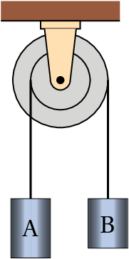
Cylinder A in the figure has a mass of 36 grams, cylinder B has a mass
of 24 grams and the moment of inertia of the double pulley is
4.43×10⁻⁷ kg·m2. The pulley is formed by
two discs, of rays 5 cm and 8 cm, glued to each
other. Each cylinder is connected to the end of a string
with the opposite end attached to the pulley, making the
pulley rotate. (a) Neglecting the friction forces
in the pulley's shaft and the air resistance, determine
the acceleration of each cylinder and say whether they are
upwards or downwards. (b) Find the tension in each
of the two strings.
In the system shown in the figure, the
mass of the wheels and pulley and the friction in their
axles can be neglected. (a) Determine the
expressions for the kinetic and potential energies of the
system, in terms of the angle
and the horizontal
position
of the cart. (b) Find the expressions
of the cart's acceleration and the angular acceleration
. (c) Find the value of the angle
in the equilibrium position of the pendulum and
say whether the equilibrium is stable or
unstable. (d) Compute the value of the cart's
acceleration when the pendulum remains in its equilibrium
position.
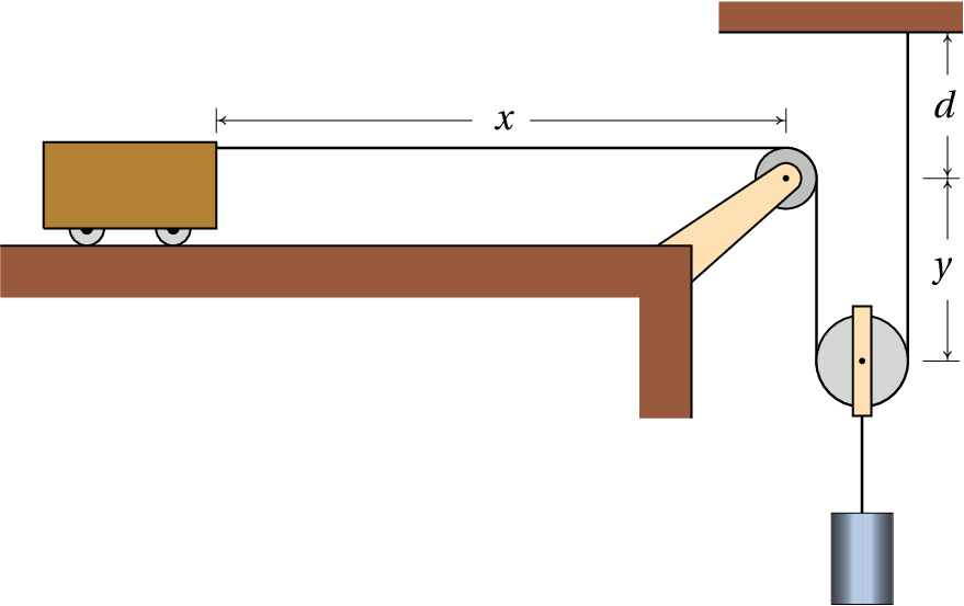
In the system shown in the figure, the
fixed pulley has mass
and the moving pulley has mass
2
(both can be considered uniform disks). The cars
mass is
and the mass of the cylinder plus the
support connecting it to the moving pulley is
. Assume that the mass of the string and the wheels,
the kinetic frictional forces on the pulley and the wheels
and the air resistance are all negligible.
(a) Show that the kinetic and potential energies of the
system in terms of the cylinder's height
are given
by the expressions:
(b) Compute the values of the accelerations of the
cylinder and the cart.
A block of mass
slides down an incline
which makes an angle
with the horizontal. The
coefficient of kinetic friction between the block and the
incline is
. Using the Lagrange equation
with a multiplier, find the expressions for the normal
force of the plane on the block and the acceleration of
the block,
(neglect the air resistance).
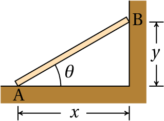
The bar in the figure is homogeneous, with
mass
and length
m, and is supported on the
floor at point A and on a wall at point B. At an initial
instant, the bar is placed at rest, with initial angle
. If the floor and wall are very smooth,
the frictional forces at points A and B are negligible and
the bar descends until the angle
decreases to
0. Assume that points A and B remain always in contact
with the floor and wall, that the air resistance is
negligible and that the thickness of the bar is much
smaller than its length.
(a) Prove that at any time the velocity of the bar's
center of mass is equal to
(b) Find the expression of the kinetic energy in terms
of the angle
.
(c) Find the expression of the gravitational potential
energy in terms of the angle
.
(d) Find the expression of the angular acceleration.
(e) Find the expression of the angular velocity.
(f) The time that the bar takes to fall to the ground is given by the
integral
.
Using the expression for
obtained in the previous
item, compute that time. (The integral is improper and
can not be calculated analytically, but can be
calculated numerically, using the function
quad_qags of Maxima.)
In a simple pendulum, with a small object
of mass
hung by a string of length
and negligible
mass, the point where the string is fixed moves up and
down according to the expression
,
where
e
are two constants.
(a) Ignoring the air resistance, determine the
expressions for the kinetic and potential energies in
terms of the angle
between the pendulum and
the vertical.
(b) Find the equation of motion for
.
(c) Explain at what values of the constants
and
the equilibrium point
will be
stable or unstable.
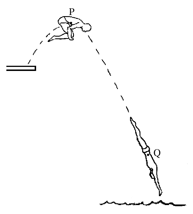
The jumper in the figure bends grabing
his legs at point P, in order to rotate faster, and then
extends his body at Q to reduce the rotation as he enters
the water. The changes in his angular velocity are a
consequence of the change in his moment of inertia.
(a) If the moment of inertia of the jumper relative to
the center of mass is
, which depends on time, write
the expressions for their kinetic and potential energies
in terms of the position (
,
) of the center of
mass and the angle of rotation
.
(b) Using the Lagrange equation for
, show that the
angular momentum,
, remains constant.
(c) If at the highest point P of the trajectory the
moment of inertia is 3.28 kg·m2 and the
angular velocity
,
and at point Q the moment of inertia is 28.2
kg·m2, determine the angular velocity of
the jumper at point Q.
The gravitational potential energy of a
celestial body with mass
, in orbit around another body
of mass
, is given by the expression (see
problem 2
of chapter 6 ):
where
is the
universal
gravitational constant and
the distance between the two bodies. It can be shown
that the possible orbits of the celestial body are always
plane. As such, the orbital motion has two degrees of
freedom that can be
and an angle
measured in
the plane of the orbit, with vertex in the body of mass
. In this system of polar coordinates, the square of
the velocity of the body with mass
is
(
).
(a) Using the Lagrange equation for
, prove that
the angular momentum
of the body with mass
, relative to the body of
mass
, remains constant.
(b) Find the equation of motion for
and show
that it depends only on
and neither on
nor
on
or
.
Answers
Questions: 1. B. 2. E. 3.
B. 4. C. 5. C.
Problems
(a)
m/s2 and
m/s2
(b)
m/s,
s.
(c)
m/s.
(a)
(b) 2.56 m/s.
(a)
(b)
(c)
(d) There is a single stable equilibrium point at the origin.
(a)
m·s−2, upwards,
m·s−2, downwards.
(b) The tension in the string attached to cylinder A is0.362 N
and the tension in the string attached to cylinder B is0.226 N.
(a) In SI units,
(b)
(c) 9.37°, stable. (d) 1.617 m/s2.
(b) Cylinder:
m/s2. Cart:
m/s2.
,
(a) The position of the center of mass is
and the velocity of the center of mass
is the derivative of that expression. Replacing
and
the result given
is obtained.
(b)
(c)
(d )
(e)
(f ) 0.3977 s.
(a) Kinetic energy:
Potential energy:
(b)
(c) If
, the equilibrium is stable, otherwise
the equilibrium is unstable.
(a)
,
(b)
, which
implies
..
(c) 0.465 s−1
(a) The Lagrange equation is:
,
which implies
constant.
(b)
, where
,
,
and
are constants.
(Click to continue)