The strong accelerations experienced in a roller coaster
are not only due to the changes of the speed, but also to
the curved trajectory. The rate of change of the speed is
only one of the components of the acceleration, namely, the
tangential component. The other component of the
acceleration depends on the curvature of the trajectory as
it is shown in this chapter.
3.1. Tangential unit vector
A tangential unit vector
can be defined at each point of the
trajectory, in the direction tangent to it and in which
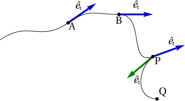
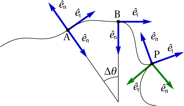
increases. Figure 3.1 shows the tangential
unit vector in three points A, B and P of a trajectory.
Figure 3.1: Tangential unit vector
in three points of the trajectory.
Note that there are two different tangential unit vectors
at point P. One of them is tangent to the curve between B
and P and the other is tangent to the curve between P and
Q. The velocity vector of an object that follows that
trajectory will always be in the direction of the tangential
unit vector, or in the opposite direction. In points such as
P, where there are two different tangential unit vectors,
the velocity will necessarily be zero; the object will be
momentarily at rest at that point, starting to move again in
a different direction from the one it had before it
stopped.
In points where the velocity is different from zero, there
is always only one tangential unit vector
, which determines the direction of the
velocity vector. Namely, the velocity vector can be
written,
(3.1)
As mentioned in
Chapter 2, the
velocity vector
is given by the derivative of the
position vector
(3.2)
Since the position vector
depends on the choice
of the origin of the reference frame, it does not have any
relation to the tangential unit vector (see
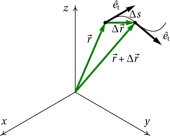
Figure 3.2). However, the
displacement vector
is independent of
the choice of origin and therefore,
equation 3.2 ensures that the
velocity vector is also independent of the choice of the
origin.
Figure 3.2: Displacement vector between two positions
and
+ Δ
.
If Δ
is the displacement vector
during a time interval
(Figure 3.2), the distance
traveled during that interval,
, is greater
than or equal to the magnitude of
Δ
. While the distance traveled is
measured along the trajectory, the magnitude of the
displacement is measured along the straight-line segment
from the initial to the final position.
The magnitude of Δ
is equal to
Δ
only when the trajectory is a straight
line, with a constant tangential unit vector. In the limit
as Δ
approaches zero, the initial and final
position are very close to each other, the direction of
Δ
is approximately the same direction
of the tangential unit vector and the magnitude of
Δ
is approximately equal to the
distance traveled
; hence, the displacement
vector is approximately equal to
. The derivative of the
position vector is then equal to
In any kind of motion, the velocity
is always equal to
the derivative of the position along the trajectory,
,
with respect to time. This is why in Chapter 1 the
derivative
was called velocity, because it is not
just the component of the velocity along the trajectory, but
the velocity itself.
3.2. Normal unit vector
The acceleration vector
is given by the
derivative of the velocity vector with respect to
time. Hence, the relation between the acceleration and the
tangential unit vector can be found differentiating both
sides of equation 3.4:
(3.5)
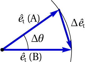
Figure 3.3: Variation of the
tangential unit vector.
Note that the derivative of the tangential unit vector is
not null because that vector is not necessarily the same at
different instants. Figure 3.3
shows how to compute the variation of the tangential unit
vector during the time interval of time shown in
Figure 3.1. The tangential unit
vectors at the beginning and end of the interval (points A
and B) were placed in a common point and the variation of
the tangential unit vector,
, is
the vector from the terminal point of the first vector to
the terminal point of the second one.
Since the magnitude of
is 1, the
terminal points of the two unit vectors
in Figure 3.3 are along an
circular arc with radius equal to 1 and angle
Δ
. If the angle is given in radians,
the length of the arc is Δ
. In the
limit as the time interval Δ
approaches
zero, the initial an final points A and B will be very close
to each other, the vector
will
become perpendicular to the trajectory and its magnitude
will be approximately equal to the length of the circular
arc, Δ
; it is then concluded that the
derivative of
is
(3.6)
where
is the
normal unit
vector, which is perpendicular to the trajectory
and
is the
angular
velocity. The expression for the
acceleration vector is obtained substituting this
derivative into
equation 3.5:
(3.7)
In conclusion, the acceleration is a vector with components
tangent and normal (perpendicular) to the trajectory. The
tangential component,
, is the
tangential
acceleration, which was introduced in
Chapter 1. The
normal component
of the acceleration is equal to the product of the
velocity
and the angular velocity
(3.8)
Since the unit vectors
and
are perpendicular in any point of the
trajectory, equation 3.7 implies
that the magnitude of the acceleration,
, is the
length of the hypotenuse of a right triangle where the other
two sides are the tangential and normal components of the
acceleration; the Pythagorean theorem applied to that
triangle leads to
(3.9)
The angle Δ
that the tangential unit
vector rotates is also to the same angle that the normal
unit vector
rotates. Figure 3.4 shows the
normal unit vectors in the same points shown in
Figure 3.1. Note that in A there
are two normal unit vectors, with opposite directions,
because the trajectory curves towards the top, before point
A, and it then curves toward the bottom after point A. That
type of point, where the direction of the curvature changes
side, is called
inflection
point.
Figure 3.4: Tangential and normal unit vectors in
some points of the trajectory.
In point P of Figure 3.4 there
are also two normal unit vectors, because as it was
explained in the previous section, there are also two
different tangential unit vectors. In any point the normal
unit vector points in the direction where the trajectory is
curving, except in the case of a rectilinear trajectory, in
which there is an infinite number of normal unit vectors
.
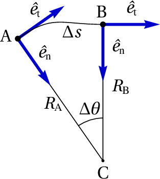
Figure 3.5: Radius of curvature.
Figure 3.5 shows the normal
unit vector in the initial position A (at time
) and
the final position B (at time
+ Δ
)
during a time interval Δ
. If
Δ
is very small, the directions of the two
unit vectors cross at a common point C. The distances from C
to the two points A and B (
e
)
are different but approach to each other in the limit
Δ
→ 0, when point C approaches the
center of curvature of the trajectory. The distance from the
center of curvature to the point on the trajectory is the
radius of curvature,
, at that point of the
trajectory.
In each point of the trajectory there is a
center of
curvature and a radius of curvature. Each
infinitesimal displacement
can be
approximated by a circular arc of radius
and angle
; the distance traveled is equal to
the length of that circular arc,
. Therefore, the
angular velocity is given by
(3.10)
Namely, in each point of the trajectory the angular
velocity
is equal to the velocity
divided by the radius of curvature
at that point. That
result can be used to express the normal acceleration
in the following way modo seguinte
(3.11)
The normal unit vector and the normal component of the
acceleration always point in the direction of the center of
curvature. Hence, the normal acceleration
is
also called
centripetal
acceleration.
Note that the tangential acceleration
can be
either positive or negative, while the normal or centripetal
acceleration is always positive, because the product
is always positive (
and
both increase, if the motion is in the direction of
the tangential unit vector, or both decrease if the motion
is in the opposite direction).
Example 3.1
The position of a particle as a function of time
is
given by the following expression (SI units):
Find the expression for the radius of curvature of the
trajectory as a function of time and compute the radius of
curvature at the two instants
= 0 and
= 1.
Solution: To obtain the expression for the radius of
curvature it is necessary to find the expressions for the
velocity and the normal acceleration. Those two expressions
can be obtained from the velocity and acceleration
vectors. In Maxima those vectors can be obtained in the
following way
The magnitudes of
and
can be found from
the square root of the product of each of these vectors with
itself. The scalar product of two vectors is computed in
Maxima writing a dot between the two lists that represent
the vectors:
Note that the acceleration is constant, which implies a
trajectory either linear or parabolic. To find the normal
component of the acceleration vector, the tangential
component can be found first through the derivative
(%i6)at: diff (v, t);
(%o6)
and the normal component is found from
equation 3.9:
(%i7)an: ratsimp (sqrt (a^2 - at^2));
(%o7)
The tangential and normal components of the acceleration
both depend on time, in spite of the acceleration being
constant; that suggests that the radius of curvature does
not remain constant and, hence, the trajectory is
parabolic. The expression for the radius of curvature can be
obtained from equation 3.11
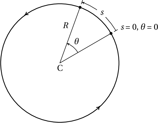
When the radius of curvature
of the trajectory remains
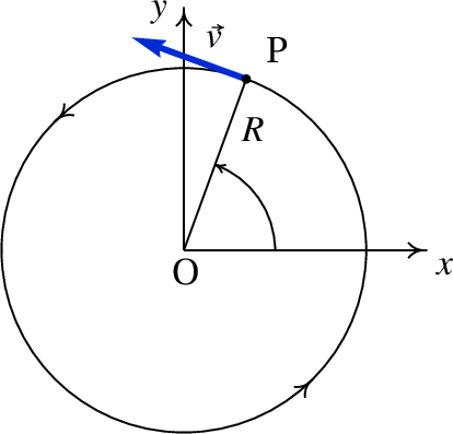
constant, the trajectory is a circumference and the motion
is circular, as
in the case shown in
Figure 3.6. Only one degree of
freedom is needed in order to give the position in any
instant; that degree of freedom can be either the position
along the circumference,
, or the angle
.
Figure 3.6: Two positions in the trajectory of a
circular motion.
If the angle and the position on the trajectory are
measured starting from the same point and both in the same
direction, the relation between them is (see
Figure 3.6)
(3.12)
Since
is constant, differentiating both sides of this
last equation leads to
(3.13)
where
is the
angular velocity. Equation 3.13
is the same as equation 3.10,
which was obtained here for the particular case of circular
motion, where
is constant, but it is a general equation
valid for any other curvilinear motion. Differentiating
both sides of equation 3.13 with
respect to time, another expression for the tangential
acceleration is found
(3.14)
where
is the angular acceleration.
The centripetal acceleration is
given by equation 3.11,
which can be written in terms of the angular
velocity
(3.15)
In the particular case when the angular velocity remains
constant, the linear velocity is constant too, the angular
and tangential accelerations are null and the motion is
called uniform circular motion. In that case,
since the angular velocity is constant, its derivative
can be computed dividing the angle for any
interval of time by the value of that interval:
(3.16)
During an interval of time equal to the
period
of the
circular motion, any point in the object moves one turn
around the circumference and the corresponding angle is
Δ
= 2
;
therefore, the period of rotation is
(3.17)
The frequency
of rotation,
, defined as the inverse of the period,
indicates the number of turns that the point moves per unit
time.
The relations among the rotation angle
, the
angular velocity
and the angular acceleration
are similar to the relations among the position on
the trajectory
, the velocity
and the tangential
acceleration
(3.18)
These are the kinematic equations for a circular motion,
which can be solved using the same methods used in
Chapter 1. The
equations 3.12,
3.13 and 3.14
show that the kinematic variables related to translation
(
,
,
) are all equal to the
corresponding kinematic variable for the circular motion,
(
,
,
), multiplied by the radius of
curvature
.
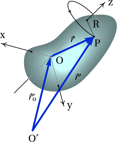
3.4. Rigid bodies kinematics
Figure 3.7 shows a moving rigid
body. Point O' is the origin of a fixed external reference
frame and point O is a point attached to the body, used as
origin for a reference frame that moves with the body.
Figure 3.7: Moving rigid body and reference frame
O
attached to it.
The position vector of a point P in the rigid body is
, with respect to the fixed reference frame, and
with respect to the reference frame moving with
the body. The relation between those two vectors is the
following
(3.19)
In the reference frame O
, in which point O is not
moving, any feasible motion of the rigid body has a line of
points, passing through O, which also remain stationary. It
would be impossible to have a motion in which all the points
in the rigid body move except O. The straight line of
stationary points is the rotation axis of the body and in
Figure 3.7 it was chosen as the
axis. In different instants the rotation axis might be
different, but the only motions studied in this chapter will
be plane rotations, defined as the motion in which the
rotation axis is always pointing in the same
direction. Thus, it is assumed that the
axis moves with
the body but keeps always the same direction. The other two
axis
and
, will be chosen also with a fixed direction
while they move with the body. Namely, with respect to the
reference frame O
the motion of the rigid body is pure
rotation, without translation.
Since the three unit vectors
,
and
of the moving frame O
remain constant,
the relations derived in
Section 2.2
are valid, so the velocity and acceleration vectors of a
point P in the rigid body, with respect to the fixed frame,
are equal to the velocity and acceleration vectors with
respect to the moving frame, plus the velocity and
acceleration vectors of point O, with respect to the fixed
frame
(3.20)
The magnitude of the position vector
and the
angle it makes with the
axis remain constant, as shown
in Figure 3.7.
Figure 3.8 shows the motion of
point P, as seen in the moving frame, which is a circular
motion on a plane parallel to the
plane, with center on
the
axis and radius
.
Figure 3.8: Trajectory of a point in the reference
frame moving with the rigid body.
In the moving frame, the velocity vector
and the
acceleration vector
are those derived in the
previous section for a circular motion; the velocity
is
then
(3.21)
and the tangential and normal components of the
acceleration
are
(3.22)
The vector expressions for the velocity and acceleration
are more conveniently obtained in a system of
cylindrical
coordinates.
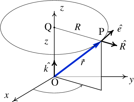
Figure 3.9 shows the three
cylindrical coordinates (
,
,
) of point
P. The plane through P and parallel to the
plane
intersects the
axis at point Q;
is the distance
between O and Q and
is the distance between P and
Q. The angle
is the angle between the projection
of the line segment
on
plane, and the positive side of the
axis.
Figure 3.9: Cylindrical coordinates.
The three perpendicular unit vectors associated to the
cylindrical coordinates are
,
and
. The unit vector
is fixed, while the
other two unit vectors point in different directions at
different points but are always on a plane parallel to the
plane. The unit vector
is in the direction of
the line segment
, pointing away
from the
axis. The direction of the unit vector
is tangent to the circumference that passes
through P and has center in Q, in the direction in which
increases.
The velocity vector
has the same direction as the
unit vector
. Since the angular velocity
is equal to the derivative of the angle
with respect to time, a positive value for
implies
rotation in the direction in which
increases and if
is negative the rotation is in the opposite
direction. Hence, an expression for the velocity vector
is
(3.23)
The tangential component of the acceleration vector
is either in the same direction of the unit vector
or in the opposite direction, and the
normal component of
is in the opposite direction
of the unit vector
. It then follows that
(3.24)
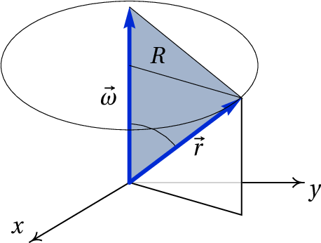
3.5. Angular velocity vector
It is convenient to define the
angular velocity vector
, with the direction of the rotation axis as
shown in Figure 3.10. The
magnitude of the vector
is the absolute
value of the angular velocity,
. There are two
opposite directions along the rotation axis; the direction
of
is chosen according to the right-hand
rule, namely, if the points of the rigid body that pass
through the positive side of the
axis move towards the
positive side of the
axis, the angular velocity vector
is then in the direction of the
axis. If those points
move towards the negative side of the
axis, the
direction of
is then opposite to the
direction of the
axis. Another way to use the
right-hand rule to determine the direction of
consists on closing the right-hand fingers
keeping the thumb open and perpendicular to the other
fingers; if the four closed fingers are positioned
following the direction of the rotation, the thumb then
points in the direction of
.
Figure 3.10: Position and angular velocity
vectors.
The advantage of using a vector to represent the angular
velocity is that the information about the rotation plane,
the direction of rotation in that plane and the rotation
speed is all contained within the vector
. Also,
equation 3.23 can then be
written in vector form, independently from the coordinates
system used, via the cross product
(3.25)
The cross product of two vectors
and
is
defined as another vector
(to be read as
cross
), with magnitude
equal to the product of the magnitudes of
and
and the sine of the angle between them. In
particular, the magnitude of
is
. Figure 3.10
shows the angle
between the two vectors; note that
is always positive, because
is between 0
and
. The product
is equal to
,
because that distance is measured on the rotation plane,
which is perpendicular to
. Therefore, the
magnitude of
is equal to
, which is also the magnitude of
.
The direction of
is
perpendicular to the plane of
and
,
following the right-hand rule from
to
:
if the right-hand index finger points in the direction of
and the middle finger points in the direction of
, then
is in the direction of the thumb.
Figure 3.10 shows the plane of
and
, which is perpendicular to the
plane so the direction of
is parallel to the
plane, perpendicular to the plane of
and
and following the direction of
the rotation.
The cross product is not commutative; namely,
and
are not
equal because they have the same magnitude but opposite
directions. Since the angle of a vector with itself is zero,
the cross product
is null. In
particular,
=
=
=
0. The cross product between two perpendicular unit vectors
is another unit vector perpendicular to the plane of
them. It is easy to check that
=
,
=
and
=
. Using this
results and the distributive law for the cross product, an
expression for the cross product
can
be obtained in terms of the Cartesian components of the two
vectors
(3.26)
and this result can be written in a more compact form with a
determinant:
(3.27)
Note that the shaded triangle in
Figure 3.10 has base equal to
and height equal to
; therefore, its area is
equal to half the magnitude of
cross
:
. In
general,
The area of a triangle formed by two vectors with a
common initial point is equal to half the magnitude of
the cross product of those vectors.
The components of the acceleration of a point in a rigid
body, relative to the reference frame moving with the body,
are given by equation 3.24,
which can be written using cross products
(3.28)
where
is the angular acceleration vector,
equal to the derivative of
with respect to
time. It should be remembered that this last expression is
only valid for plane rotations, where the directions of the
three axis of the moving frame remain constant and the
differentiation of
to obtain
must be carried out with respect to that moving frame.
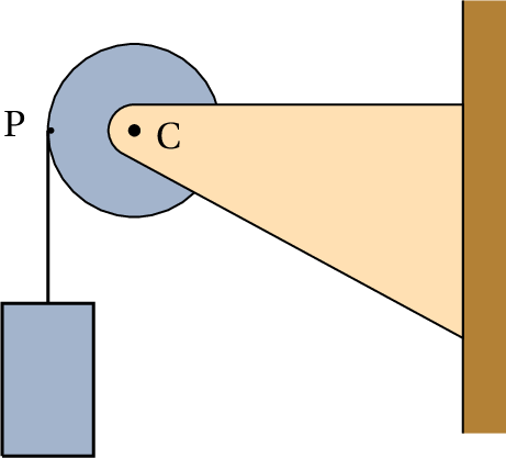
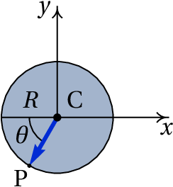
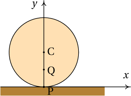
Example 3.2
A string is attached and winded around a pulley with
radius of 5 cm and a block is hanged to the free end
of the string (see Figure). Initially the block and the
pulley are at rest and point P in the pulley's surface is
at the same height as the pulley's center C. The block
then starts falling, with constant acceleration equal to
/4. Find the velocity and acceleration of point P at
the instant when the block has fallen for two seconds.
Solution. Let us choose a system of Cartesian
coordinates with origin at the center of the pulley's
center, as shown in the figure. The figure also shows point
P after the pulley has already rotated an angle
from the initial position. The position vector for P at that
moment is
The velocity of point P can be given in terms of the
angular velocity of the pulley, which can be obtained from
the velocity of the block. An expression for the velocity of
the block can be derived integrating the equation
Since all points in the string have that same velocity and
the points on the surface of the pulley follow the same
motion as the string,
is also the velocity for any
point in the surface of the pulley and the angular velocity
of the pulley is then
. The angular
velocity vector is perpendicular to the
plane and since
the rotation is in the anti-clockwise direction
The velocity vector of point P is equal to the cross
product of the angular velocity vector and the position
vector of point P
If the center of the pulley were moving, it would also be
necessary to add its velocity to this last result. Note that
the same result could have been obtained differentiating
with respect to time, but it would have
been necessary to find the expression for
as a
function of time.
The angular acceleration vector is the derivative of the
angular velocity vector with respect to time
and the acceleration vector of point P is then
The expression for
as a function of time is found
by integrating the equation
substituting the values
= 2,
= 0.05 and
= 9.8,
in SI units, the velocity and acceleration at that time are
found
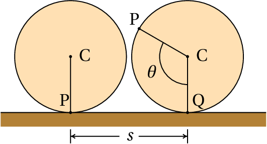
3.6. Dependent translations and rotations
In a wheel rolling over a surface without sliding, the
rotation angle and the displacement of the wheel's center
are interrelated. Figure 3.11
shows a wheel of radius
moving to the right, rolling
over a surface without sliding.
Figure 3.11: Wheel rolling without
sliding.
If a point P on the surface of the wheel is initially in
contact with the surface, after that point rotates an angle
the center of the wheel moves a distance
. The
circular arc
is equal to
, because all the
points in that arc were in contact with a point on the
surface
(3.29)
Differentiating both sides of this equation, a relation
between the velocity of the center C and the angular
velocity is found
(3.30)
and differentiating one more time leads to the conclusion
that the tangential acceleration of C is equal to the
product of the radius and the angular acceleration
(3.31)
In the case of pulleys and strings, if the string does not
slide over the surface of the pulley while this turns, the
points on the surface of the pulley will have the same
velocity as the string. The velocity of the points on the
surface of the pulley relative to the center is equal to the
velocity of those points, minus the velocity of the center
of the pulley. That relative velocity divided by the radius
of the pulley gives the angular velocity of the pulley
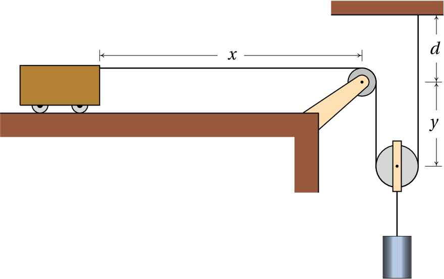
Example 3.3
The radius of the static pulley in the system shown in
the figure is 3 cm and the radius of the moving
pulley is 5 cm. Find the velocity of the cart and the
angular velocities of the pulleys, at a moment when the
cylinder is falling with velocity equal to 1.5 m/s,
assuming that the string does not slide over the
pulleys.
Solution. This system has already been analyzed in
Section 2.4
where it was shown that the velocity of the cart is always
twice as great as the velocity of the cylinder. Therefore,
the velocity of the cart at the instant considered is equal
to 3 m/s.
In the static pulley, the velocity of the points on the
surface are equal to the velocity of the cart, 3 m/s;
hence, the angular velocity of that pulley is
The center of the moving pulley falls with the same
velocity as the cylinder, 1.5 m/s. The point of the
surface which is to the right of the center of the pulley is
at rest; therefore, relative to the center of the pulley
that point moves upward at 1.5 m/s. The point on the
surface of the pulley which is to the left of the center
moves downward with the same velocity as the cart,
3 m/s, so its velocity relative to the center of the
pulley is 1.5 m/s downwards. The angular velocity of
the moving pulley is then
The part of the string on the right of the moving pulley is
static and thus could be regarded as a vertical surface over
which the pulley is rolling down as a wheel moving over a
surface. Therefore, the velocity of the center of the
pulley, which is also equal to the velocity of the cylinder,
is given by the angular velocity of the pulley times its
radius. That's an alternative way to explain why the
velocity of the cart is twice as great as the velocity of
the cylinder, because the diameter of the pulley is twice as
great as its radius.
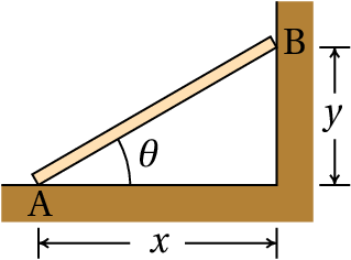
Example 3.4
The 2 meter bar shown in the figure is in contact with
the horizontal floor in point A and with the vertical wall
in point B. Initially, at
, the distance
is equal
to
m and point A starts moving to the left with
speed that depends on
according to the following
expression (SI units)
Meanwhile, point B moves down the wall. Find the angular
velocity of the bar and the speed of point B, as functions
of
.
Solution. This system has only one degree of
freedom, which can be chosen as the distance
. Since the
length of the bar is 2,
and
are related to
according to
The velocities of A and B are equal to the absolute value
of the derivatives of
and
with respect to time and
are obtained differentiating the two relations above
where
is the angular velocity of the
bar.
From the Pythagorean theorem,
. The angular
velocity is obtained substituting this expression into the
equation for
and substituting this expression into the equation for
leads to
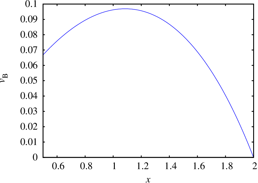
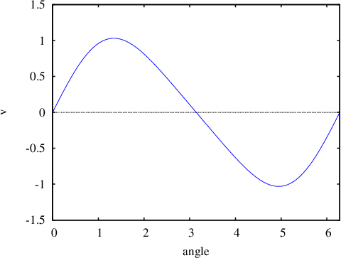
Figure 3.12 shows the plot of
the speed of B, from the initial instant when
until
the instant when the bar stops at the floor, when
. That speed has a maximum value of around
9.7 cm/s, when the angle
is around
57°.
Figure 3.12: Speed of point B with respect to
(SI units).
Questions
(To check your answer, click on it.)
During the time interval
0 <
< 1, the velocity of an
object as a function of time is
. Knowing that the object follows a
rectilinear trajectory, choose the correct expression for
the acceleration from the following list.
The angular acceleration of an object with circular
motion is constant and equal to
radian/s2. If the object starts
moving from rest, in how many seconds will it complete 3
turns?
A point in an object follows a curved trajectory with
constant velocity. Which of the following statements is
correct?
The acceleration vector is perpendicular to the trajectory.
The magnitude of the acceleration vector is constant.
The acceleration vector is tangent to the trajectory.
The acceleration vector is constant.
The acceleration vector is null.
A projectile is thrown with initial velocity
in
a direction that makes an angle
with the
horizontal. Find the radius of curvature of the parabolic
trajectory at the initial instant.
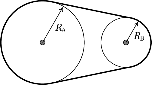
The rotation of a wheel of radius
is being
transmitted to another wheel of radius
by a belt
that moves with the two wheels, without sliding on their
surfaces. Find the relation between the angular velocities
and
of the two wheels.
Problems
During the time interval
the magnitudes
of the velocity and the acceleration of a particle with
three-dimensional motion are:
and
(SI units). Find the
expressions, in that same time interval, for:
The tangential component of the acceleration.
The normal component of the acceleration.
The radius of curvature.
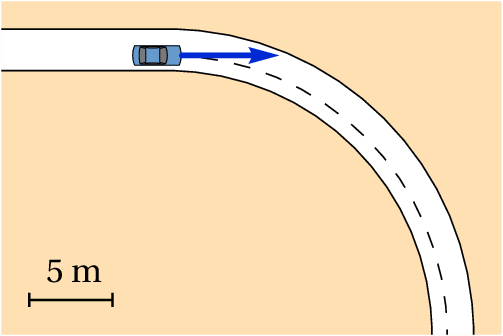
A car driver enters a curve at
72 km/h, and slows down, making the speed decrease at
a constant rate of 4.5 km/h each second. Make an
estimate for the value of the radius of the curve using
the scale shown in the figure. Find the acceleration of
the car 4 seconds after the driver started to slow
down.
The equation of the trajectory of an
object is:
(SI units and angles in
radians). (a) Prove that the motion is circular and
uniform. (b) Find the angular velocity of the
object and its rotational period. (c) Find the
position of the center of the circular trajectory.
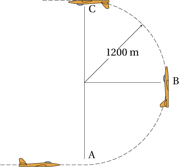
An airplane race pilot performs a vertical
loop following a semi-circumference of radius
1200 m. The airplane's velocity in point A, at the
start of the loop, is 160 m/s and in point C, at the
end of the loop it is 140 m/s. Find the acceleration
in point B, at the middle of the loop, assuming that the
tangential acceleration remains constant during the loop
(note that it is also negative).
(a) Find the area of the
triangle with vertices A, B and C with Cartesian
coordinates A = (3, 5, 4),
B = (−1,2,1) and
C = (2,−2,2). (b) Prove
the law of
sines, for a plane triangle with sides of
length
,
and
,
where
,
and
are the angles
opposite to the sides
,
and
respectively.
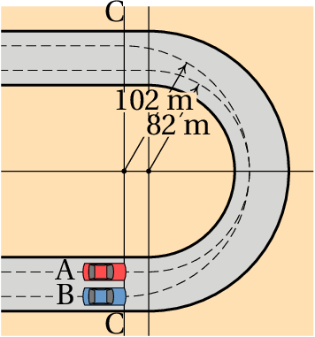
Two cars A and B go through the curve
shown in the figure following different paths. From a
point on the line C, car B follows a semi-circumference of
radius 102 m; until another point on line C. Car A
moves from the line C following a straight line segment,
it then follows a semi-circumference of radius 82 m
and moves to another point on line C following another
straight line segment. Both cars move at the highest speed
that they can have without the tires sliding out of the
circular path, which for the type of tires used means that
the normal acceleration will have the maximum value of
0.8
, where
is the acceleration of
gravity. Find the times that both cars need to complete
the curve, from the initial point on the line C, to the
final point on the same line.
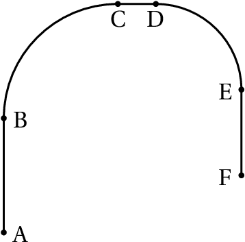
A particle follows the path shown in the
figure, starting from rest at A and then speeding up with
constant acceleration until B. From B to E the speed of the
particle remains constant at 10 m/s and at E the
particle slows down, with constant acceleration, untill it
stops at point F. The distance AB is 60 cm, CD is
20 cm and EF is 45 cm; arc BC has radius of
60 cm and arc DE has radius of 45 cm. Find:
The magnitude of the acceleration of the particle in
each of the paths AB, BC, CD, DE and EF.
The total time of the motion from A to F and the
average velocity in that motion.
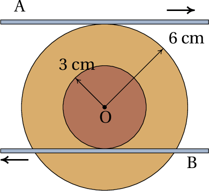
A disk of radius 3 cm is glued to
another disk of radius 6 cm, with a common axis, as
shown in the figure. The horizontal bar A moves to the
right at 10 m/s, keeping in contact with the bigger
disk and without sliding on its surface. At the same
time, the horizontal bar B moves to the left at
35 m/s, keeping in contact with the smaller disk and
without sliding on its surface. Determine the direction
of motion of the center O and find the velocity of O and
the angular velocity of the disks.
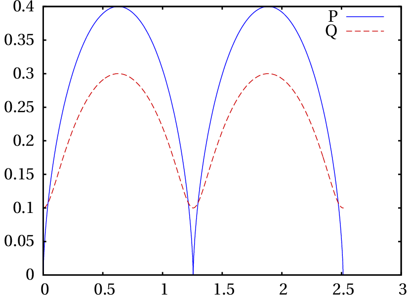
A wheel of radius equal to 20 cm
rolls without sliding over a plane horizontal surface,
along the
axis. At time
the wheel's
center is in
and
cm and points P and Q in the wheel
are in
with
and
cm. The velocity of the wheel's
center remains constant and equal to 2 m/s.
(a) Determine the time it takes the wheel to
complete two turns. (b) Plot the trajectories of
points P and Q in the interval of time corresponding to
the two turns.
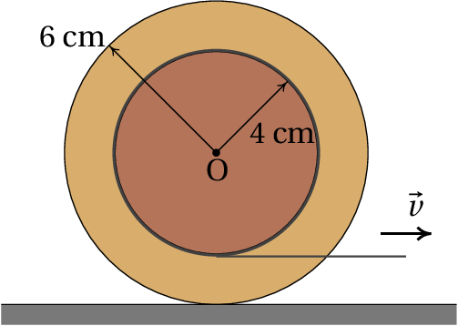
A dumbbell has two disks with radius of 6
cm, connected by a cylindrical bar with radius of 4 cm. A
long strip of paper is taped and rolled around the bar as
shown in the figure. The dumbbell is then placed on a flat
horizontal surface and the paper strip is pulled
horizontally with a constant speed of 2.5 cm/s, making the
dumbbell roll over the surface without sliding.
Find the angular velocity of the dumbbell.
Explain in which direction will move the point O in
the axis of the bar and the disks and find its
velocity.
How many centimeters of the paper strip will be
wound or unwound per second?
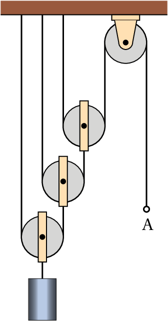
All the pulleys in the configuration
shown in the Figure have the same radius of 5 cm. Find
the angular velocities of the four pulleys when the ring
A is pulled down at 2 m/s.
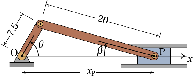
The Figure shows a slider-crank mechanism
used to convert circular motion to reciprocating
motion (linear motion back and forth) or the other way
around. The crank is the bar of length
that
rotates around a fixed axis through point O, and the
bar of length
used to link the crank to the
sliding piston P is called the connecting rod.
Choosing an
axis along the direction in which the
piston moves and through the points O and P, and if
is the angle between the crank and the
axis:
Show that the position
of point P, as a
as a function of
, is given by
Find the relation between the angular
velocity of the crank and the velocity of the
piston.
The length
of the connecting rod
must be greater than
. Make the plot of the
velocity of the piston as a function of
, in the
case
,
and
in the direction shown in the
figure (SI units), and show that the speed of the piston
is zero when
equals 0 or 180°.
Answers
Questions:1. E. 2. B. 3.
A. 4. E. 5. A.
Problems
(a)
(b)
(c)
With a radius of 16 m, the acceleration is approximately
14 m/s2
(a) The magnitude of the velocity vector is found
to be
and the components of the
acceleration are found to be
and
. Therefore, the motion is
uniform, because the velocity remains constant, and it is
circular because the motion is on a plane and the radius
of curvature,
, is constant. (b)
rad/s,
(seconds). (c) coordinates (4, 0).
18.85 m/s2
(a) 14.79 (b) The three products
(
), (
) and
(
) are all equal to twice the area of
the triangle; equating each two of those three products,
the three equations given are found.
11.74 s for car A and 11.33 s for car B.
(a) 83.33 m/s2 in AB,
111.11 m/s2 in EF,
166.67 m/s2 in BC and
222.22 m/s2 in DE. (b) 0.395 s
and 7.34 m/s.
Point O moves to the left, with velocity
m/s and the angular
velocity of disks is
s−1.
(a) 1.26 s (b)
(a) 1.25 s−1, in the clockwise
direction. (b) To the right, with speed
7.5 cm/s. (c) 5 cm (the strip winds up more around
the bar, because the bar is rotating clockwise).
From left to right, 5 s−1,
10 s−1, 20 s−1
and 40 s−1.
(b)
(c) When
equals 0 or 180°,
and
are both null and the
expression for the velocity of Point P becomes 0.
Wrong
In a rectilinear motion the acceleration is equal to the
tangential acceleration, which is the derivative of the
velocity with respect to
.
(click to continue)
Wrong
In a rectilinear motion the acceleration is equal to the
tangential acceleration, which is the derivative of the
velocity with respect to
.
(click to continue)
Wrong
In a rectilinear motion the acceleration is equal to the
tangential acceleration, which is the derivative of the
velocity with respect to
.
(click to continue)
Wrong
In a rectilinear motion the acceleration is equal to the
tangential acceleration, which is the derivative of the
velocity with respect to
.
(click to continue)
Correct
In a rectilinear motion the acceleration is equal to the
tangential acceleration, which is the derivative of the
velocity with respect to
.
(click to continue)
Wrong
The angular acceleration must be integrated with respect to
time, to find the expression for the angular velocity and
that expression must be integrated again to obtain the
expression for the angle. Three turns mean an angle of
.
(click to continue)
Correct
The angular acceleration must be integrated with respect to
time, to find the expression for the angular velocity and
that expression must be integrated again to obtain the
expression for the angle. Three turns mean an angle of
.
(click to continue)
Wrong
The angular acceleration must be integrated with respect to
time, to find the expression for the angular velocity and
that expression must be integrated again to obtain the
expression for the angle. Three turns mean an angle of
.
(click to continue)
Wrong
The angular acceleration must be integrated with respect to
time, to find the expression for the angular velocity and
that expression must be integrated again to obtain the
expression for the angle. Three turns mean an angle of
.
(click to continue)
Wrong
The angular acceleration must be integrated with respect to
time, to find the expression for the angular velocity and
that expression must be integrated again to obtain the
expression for the angle. Three turns mean an angle of
.
(click to continue)
Correct
The acceleration vector has only normal component because the
tangential acceleration (derivative of the velocity with
respect to time) is zero.
(click to continue)
Wrong
The normal acceleration, related to the change of direction
of the velocity, could have any value; therefore, the
magnitude of the acceleration can change.
(click to continue)
Wrong
The acceleration vector can't be tangent to the trajectory,
because the tangential component of the acceleration
(derivative of the velocity with respect to time) is
zero.
(click to continue)
Wrong
There are curvilinear motions with constant
acceleration vector. An example is the parabolic motion of a
projectile. However, since the normal acceleration has
different directions at different points in the trajectory,
there must be also a variable tangential acceleration that
compensates those changes. In this case, that cannot happen
because the tangential acceleration is zero.
(click to continue)
Wrong
If the acceleration vector was null, the trajectory should be
a straight line, but in this case it is curved.
(click to continue)
Wrong
The radius of curvature is equal to the square of the
velocity, divided by the normal acceleration. The normal
acceleration is obtained projecting the acceleration of
gravity vector along the direction of the velocity
vector.
(click to continue)
Wrong
The radius of curvature is equal to the square of the
velocity, divided by the normal acceleration. The normal
acceleration is obtained projecting the acceleration of
gravity vector along the direction of the velocity
vector.
(click to continue)
Wrong
The radius of curvature is equal to the square of the
velocity, divided by the normal acceleration. The normal
acceleration is obtained projecting the acceleration of
gravity vector along the direction of the velocity
vector.
(click to continue)
Wrong
The radius of curvature is equal to the square of the
velocity, divided by the normal acceleration. The normal
acceleration is obtained projecting the acceleration of
gravity vector along the direction of the velocity
vector.
Correct
The radius of curvature is equal to the square of the
velocity, divided by the normal acceleration. The normal
acceleration is obtained projecting the acceleration of
gravity vector along the direction of the velocity
vector.
(click to continue)
Correct
The speed of any point in the belt is the same and hence,
the speeds of the points on the surfaces of the two wheels
must be the same.
(click to continue)
Wrong
The speed of any point in the belt is the same and hence,
the speeds of the points on the surfaces of the two wheels
must be the same.
(click to continue)
Wrong
The speed of any point in the belt is the same and hence,
the speeds of the points on the surfaces of the two wheels
must be the same.
(click to continue)
Wrong
The speed of any point in the belt is the same and hence,
the speeds of the points on the surfaces of the two wheels
must be the same.
(click to continue)
Wrong
The speed of any point in the belt is the same and hence,
the speeds of the points on the surfaces of the two wheels
must be the same.
 An airplane race pilot performs a vertical
loop following a semi-circumference of radius
1200 m. The airplane's velocity in point A, at the
start of the loop, is 160 m/s and in point C, at the
end of the loop it is 140 m/s. Find the acceleration
in point B, at the middle of the loop, assuming that the
tangential acceleration remains constant during the loop
(note that it is also negative).
An airplane race pilot performs a vertical
loop following a semi-circumference of radius
1200 m. The airplane's velocity in point A, at the
start of the loop, is 160 m/s and in point C, at the
end of the loop it is 140 m/s. Find the acceleration
in point B, at the middle of the loop, assuming that the
tangential acceleration remains constant during the loop
(note that it is also negative).
 Two cars A and B go through the curve
shown in the figure following different paths. From a
point on the line C, car B follows a semi-circumference of
radius 102 m; until another point on line C. Car A
moves from the line C following a straight line segment,
it then follows a semi-circumference of radius 82 m
and moves to another point on line C following another
straight line segment. Both cars move at the highest speed
that they can have without the tires sliding out of the
circular path, which for the type of tires used means that
the normal acceleration will have the maximum value of
0.8
, where
is the acceleration of
gravity. Find the times that both cars need to complete
the curve, from the initial point on the line C, to the
final point on the same line.
Two cars A and B go through the curve
shown in the figure following different paths. From a
point on the line C, car B follows a semi-circumference of
radius 102 m; until another point on line C. Car A
moves from the line C following a straight line segment,
it then follows a semi-circumference of radius 82 m
and moves to another point on line C following another
straight line segment. Both cars move at the highest speed
that they can have without the tires sliding out of the
circular path, which for the type of tires used means that
the normal acceleration will have the maximum value of
0.8
, where
is the acceleration of
gravity. Find the times that both cars need to complete
the curve, from the initial point on the line C, to the
final point on the same line.
 A particle follows the path shown in the
figure, starting from rest at A and then speeding up with
constant acceleration until B. From B to E the speed of the
particle remains constant at 10 m/s and at E the
particle slows down, with constant acceleration, untill it
stops at point F. The distance AB is 60 cm, CD is
20 cm and EF is 45 cm; arc BC has radius of
60 cm and arc DE has radius of 45 cm. Find:
A particle follows the path shown in the
figure, starting from rest at A and then speeding up with
constant acceleration until B. From B to E the speed of the
particle remains constant at 10 m/s and at E the
particle slows down, with constant acceleration, untill it
stops at point F. The distance AB is 60 cm, CD is
20 cm and EF is 45 cm; arc BC has radius of
60 cm and arc DE has radius of 45 cm. Find:
 A disk of radius 3 cm is glued to
another disk of radius 6 cm, with a common axis, as
shown in the figure. The horizontal bar A moves to the
right at 10 m/s, keeping in contact with the bigger
disk and without sliding on its surface. At the same
time, the horizontal bar B moves to the left at
35 m/s, keeping in contact with the smaller disk and
without sliding on its surface. Determine the direction
of motion of the center O and find the velocity of O and
the angular velocity of the disks.
A disk of radius 3 cm is glued to
another disk of radius 6 cm, with a common axis, as
shown in the figure. The horizontal bar A moves to the
right at 10 m/s, keeping in contact with the bigger
disk and without sliding on its surface. At the same
time, the horizontal bar B moves to the left at
35 m/s, keeping in contact with the smaller disk and
without sliding on its surface. Determine the direction
of motion of the center O and find the velocity of O and
the angular velocity of the disks.
 All the pulleys in the configuration
shown in the Figure have the same radius of 5 cm. Find
the angular velocities of the four pulleys when the ring
A is pulled down at 2 m/s.
All the pulleys in the configuration
shown in the Figure have the same radius of 5 cm. Find
the angular velocities of the four pulleys when the ring
A is pulled down at 2 m/s.
In a rectilinear motion the acceleration is equal to the tangential acceleration, which is the derivative of the velocity with respect to .
(click to continue)