In order to make a curve with a bicycle or a motorcycle there must be
sufficient friction between the tires and the road, because the
frictional force provides the centripetal force that makes the bike
follow the curved trajectory. But the frictional force also makes the
rider and the bike rotate sideways in the direction opposite to the
center of the curve; to counteract that rotation the rider tilts with
the bike, making their weights produce a tendency to rotate in the
opposite direction. The tendency to rotate produced by a force is
called moment and will be studied in this chapter. The high speeds in
motorcycle races imply larger tilt angles. To make the motrocycle tilt
more, the rider first turns the wheel in the opposite sense of the
curve and moves his body away from the motorcycle in the direction of
the center of the curve.
5.1. Sliding vectors
The vectors introduced in chapter
2 are free vectors, which are considered equal if they have the
same magnitude, direction and sense, regardless of the point of the
space where they are. In the case of forces, it is not enough to know
their magnitude, direction and sense. For example, when a force is
applied to a door to close it, besides the magnitude, direction and
sense of the force, the point at which that force is applied will also
be important. The further away from the hinges the force is applied,
the easier it is to close the door. The force required to close the
door would be very high if it was applied at a point near the hinges.
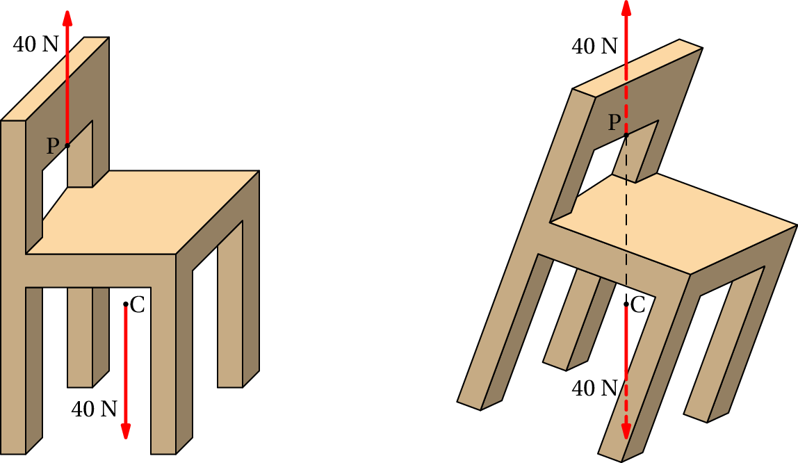
Suppose we want to move a chair to another place, lifting it with just
one hand. If the chair weights 40 N, and its center of gravity is at
the point C, as shown in figure 5.1, we
would probably put our hand at a point P on the back of the chair and
apply an upward force of 40 N to lift it. As the chair moves up, it
will rotate until it reaches an equilibrium position as shown on the
right-hand side of the figure, where the weight and the force applied
by the hand are in the same vertical line. If we could apply the
upward force in a point in the same vertical line as the center of
gravity C, the chair would go straight up without rotating.
Figure 5.1: A chair of weight 40 N being lifted with an upward force.
We conclude that to predict the effect of a force it is necessary to
know its magnitude, direction, sense and also
its line of
action, which is the straight line passing through the
point where the force is applied, in the direction of the force. A
force produces different effects if it is moved to a different line of
action, even if its magnitude, direction and sense are kept equal.
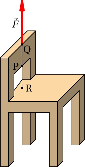
Figure 5.2: Three equivalent points.
These kind of vectors, with a specific line of action, are
called slidingvectors. The point
where they are applied is not important, as long as it is in their
line of action. In the example of the chair being lifted, the same
upward force
could have been applied at points Q or R in
figure 5.2, which are in the same vertical
line as P, and the effect would have been the same. The chair would
rotate in the same direction, with the same angular
acceleration. Therefore, it is equivalent to assume that
is
applied in P, Q, R or any other point in its line of action. However,
even if the initial effect is the same, once the chair starts to
rotate, the higher the point where
is applied, the more the
chair will rotate until the line of action of its weight coincides
with the line of action of
, reaching the equilibrium
position.
Whenever it was necessary to add forces
in chapter 4, we assumed that they
could be moved freely and added together as free vectors, using
the parallelogram
rule. In the following sections it is shown that this sum of
forces as if they were free vectors is not wrong, as long as the
rotation effect introduced when moving a force to a different line of
action is also taken into account. The translation of a body is
determined by the resultant force, which can be obtained adding all
external forces as free vectors. The rotation, or lack of it, is also
determined by the external forces but regarded as sliding vectors and
not as free vectors.
5.2. Superposition of forces
To determine how forces and other sliding vectors must be added, let
us start by the simplest case, when the forces to be added have the
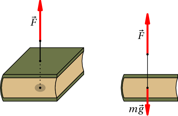
same line of action. For example, if we are going to lift a book that
is resting on a horizontal table, as in
figure 5.3, in order to apply an upward
force in the same vertical line as the center of gravity we could
drill a hole through the book, going through the center of gravity,
and pass a string through the hole attaching it to a washer on the
bottom of the book.
Figure 5.3: Collinear forces.
When we pull up the string with a force
, that force will be
collinear with
the weight; namely, they act along the same line of action, so the two
forces can be moved to a common point in that line, and added as free
vectors. If
is bigger than the weight
, the book
accelerates upwards without rotating;
is then reduced to
to maintain a constant speed. Once the book is approaching the
height where we want it to be, we reduce the force on the string even
more, making it smaller that the weight so the speed will decrease
until it stops, at which point we increase the force again, balancing
the weight. book stop at some height. We are so used to following
that process every time we lift an object, that we might not be aware
of its complexity. But if we have to program a robot arm to do it, we
would have to follow all of those steps.
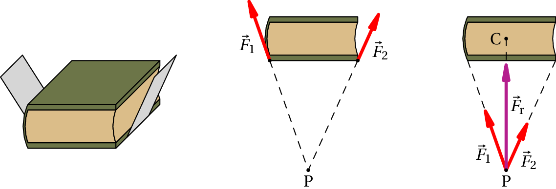
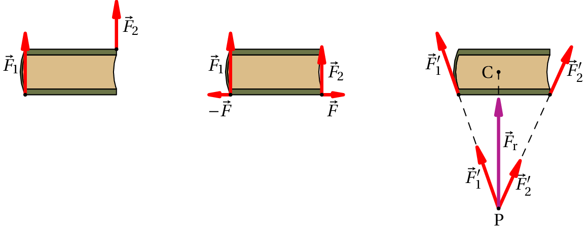
If we don't want to drill a hole through the book to lift it, we could
also pass a strip of paper under it, as shown in the left side of
figure 5.4, and pull up the two ends of
the strip keeping the book horizontal as it raises. We would then be
applying two forces
and
as shown in the middle
of the figure.
Figure 5.4: Addition of concurrent forces.
Those two forces are called concurrent, because their lines of action
cross each other at a point P. We can then move each force along its
line of action, to the point P, and add them there as free vectors to
give the resultant force
, as shown in the right
side of figure 5.4. Notice that, if the
book is lifted keeping it horizontal, it does not rotate so the
resultant force
must be collinear with the weight
. That means that point in
figure 5.4 the point P and the center of
gravity C of the book must be in the same vertical line; the
magnitudes and directions of the two forces
and
must be such that their lines of action cross in a point
which is in the same vertical as the center of gravity.
When the lines of action of two forces
and
are
parallel, as is the case in figure 5.5,
we can use the following procedure to add them: two additional
collinear forces
and
are added, in a direction
perpendicular to the lines of action of
and
,
as shown in the middle of the figure. That does not alter the system,
since the sum of those two additional forces is zero. The force
is then added together with
, in their common
point, giving a force
, and
is added together
with
, in their common point, giving a force
. These two new forces
and
are
now concurrent and can be added in their common point P (right side of
figure 5.5) giving the resultant force
.
Figure 5.5: Addition of parallel forces.
Notice that the resultant force
is also in the
same direction as the original forces and with magnitude equal to the
sum of the magnitudes of
and
, since
teh sum of the free vectors
and
at P
equals the sum of
and
as free vectors:
(5.1)
If
and
had opposite directions, the resultant
force would be inn the direction of the force with the biggest
magnitude and the magnitude of the resultant would bee equal to the
difference between the magnitudes of the two forces.
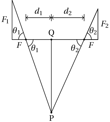
Figure 5.6: Line of action of the resultant.
The line of action of the resultant force
will
alos be parallel to the lines of action of the two forces
and
. To determine the distances
and
between
the lines of action of the parallel forces
and
, and their resultant
, we observe in
figure 5.6 that the distance between the
common point P in the lines of action of
and
and point Q, where the line of action of the resultant crosses the
segment joining the points where
and
are
applied, is equal to:
(5.2)
where
and
are the angles that
and
make with the perpendicular to their lines of action.
Since
is the sum of the two perpendicular forces
and
, and
is the sum of the two
perpendicular forces
and
, the tangents of those
two angles are
(5.3)
and substituting those two expressions into
equation 5.2, we arrive to the
so-called law
of the lever:
(5.4)
Therefore, to lift the book with two vertical forces without making
it rotate, it would be necessary that the ratio between the magnitude
of the forces,
, be the inverse of the ratio between their
distances of their lines of action to the center of gravity,
.
5.3. Moments and couples
The law of the lever can be explained by introducing the concept
of moment of a force about a point. The moment of a force
about a point O is defined as the product of the magnitude
of the force by the distance
from point O to the line of action of
:
(5.5)
is called the moment
arm of the force and the moment about a point is also called
torque. The moment
measures the rotational effect
produced by the force when point O is fixed. The further away the
action line of the force is from point O, the bigger the rotation
effect it produces. This explains why it is more difficult to close or
open a door if the force is applied too close to the hinges: the
moment of the force about the hinges is small when its line of action
is close to the rotation axis of the door.
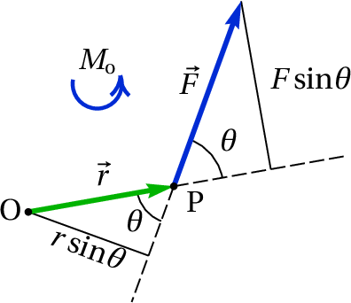
Figure 5.7: Moment of a force.
If
is the position vector of the point P where
the force
is applied, relative to point O, the
moment arm of the force about point O is equal to
, where
is the angle between the
vectors
and
(figure 5.7). We then conclude
that the moment of the force about point O is equal to,
(5.6)
It should be noted that (
) is the component
of the force in the direction perpendicular to the position
vector
, that is, the moment of the force about O
is also equal to the product of the distance
,
from its point of application to point O, times the
component of the force perpendicular to
. The
moment produced by a force is due solely to its
component perpendicular to the segment from the reference
point to the point where the force is applied.
Equation 5.6 shows that the
moment of a force is also equal to the magnitude of
the cross
product between the position vector and the force. It
is convenient to define the vector moment:
(5.7)
The vector
produces a rotation about O on a plane
perpendicular to
and in the sense given by the
right-had rule. In figure 5.7 the moment
is a vector that points outside of the figure and can be represented
by an arc with an arrow in the sense of the rotation.
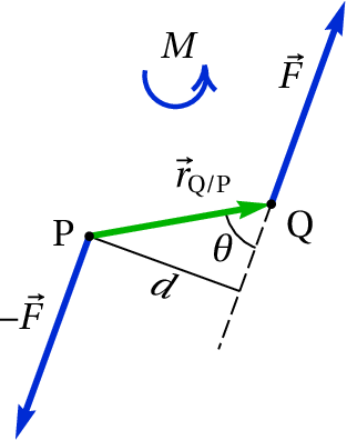
Figure 5.8: Couple.
The method described to add parallel forces would fail when the two
forces constitute a couple,
which are two parallel forces with the same magnitude but opposite
directions, as in figure 5.8. In that case
and
would still be parallel and could not be
added as concurrent forces. However, in that case equation 5.1 shows that the resultant will be zero. Thus, a couple will
not produce any translation, just rotation. The total moment about the origin
O is the sum of the moments of the two forces:
(5.8)
The two position vectors of the points Q and P depend on
the choice of the origin O, but their difference
does not change if
the origin O is moved to another point.
That means that the couple produces a moment
that does not
depend on any reference point,
(5.9)
The couple of the two forces in figure 5.8
is a vector pointing out of the figure, represented by the circular
arc with an arrow in the counterclockwise direction.
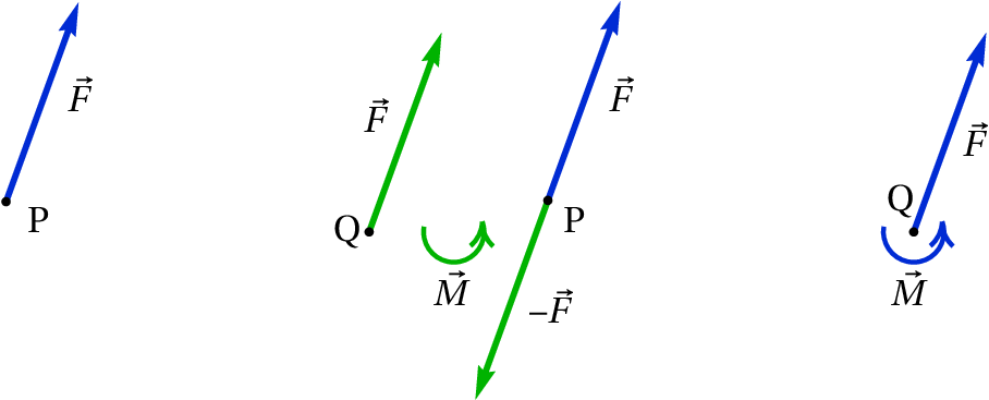
A force
applied at a point P can be moved to another point
Q, outside its line of action, using the procedure illustrated in
figure 5.9: we add two equal and opposite
forces
and
in points P and Q, which a moment that
we will call
(in the clockwise sense in the case of the
figure); in order to keep the system the same, we must then add also a
couple
(in the anti-clockwise sense) which will balance the
moment
. We are then left with two equal and opposite forces
at point P, which will eliminate each other leaving only the force
at point P, and the couple
:
(5.10)
which is equal to the moment
that the original force
in P produced with respect to the point Q where it was moved.
Figure 5.9: Procedure to move a force from a point P to another
point Q.
We can then conclude that the resultant of a system of force is equal
to their sum as free vectors and can be placed at any point Q,
provided we also include a resultant couple which is equal to the sum
of the moments of all the forces with respect to that point.
When the direction of the forces are on the same plane, it will be
convenient to use Cartesian coordinates
and
on that plane, with
origin at the point where we want to place the resultant force.
With that choice of coordinates, the moment of each force
with respect to the origin will only have a
component, equal to
the 2-by-2 determinant:
(5.11)
where
and
are the coordinates of the point where force
acts. With a
total of
forces, all on the
plane, the resultant force and
couple are the following
(5.12)
The resultant force can then be moved to another line of
action, a distance
from
its line of action in Q, in order to eliminate the resultant
couple
leaving just the resultant force.
When the lines of action of the forces are not in the same plane,
the resultant couple
will also include a
component parallel to the resultant force
, which
cannot be eliminated by moving that resultant force to another point.
In that case the simplest form of the resultant is a force and a couple
in the same direction.
5.4. Rigid bodies in equilibrium
A rigid body is in equilibrium if the sum of all forces acting on it
gives a resultant force
and couple
both equal to zero. Notice that in that case, the
resultant couple will be zero with respect to any point, because
moving the resultant force
to any other point
does not introduce any additional moment. When a rigid body is in
equilibrium, it will not have any linear or angular acceleration;
therefore, it could be in a static position or moving with constant
velocity (linear and/or angular).
Thus, when we know that a rigid body is static or moving with constant
velocity, the equilibrium conditions establish that the vector sum
of all external forces is equal to zero, and the sum of the moments
of those forces, relative to any reference point, is also equal to zero.
zero.
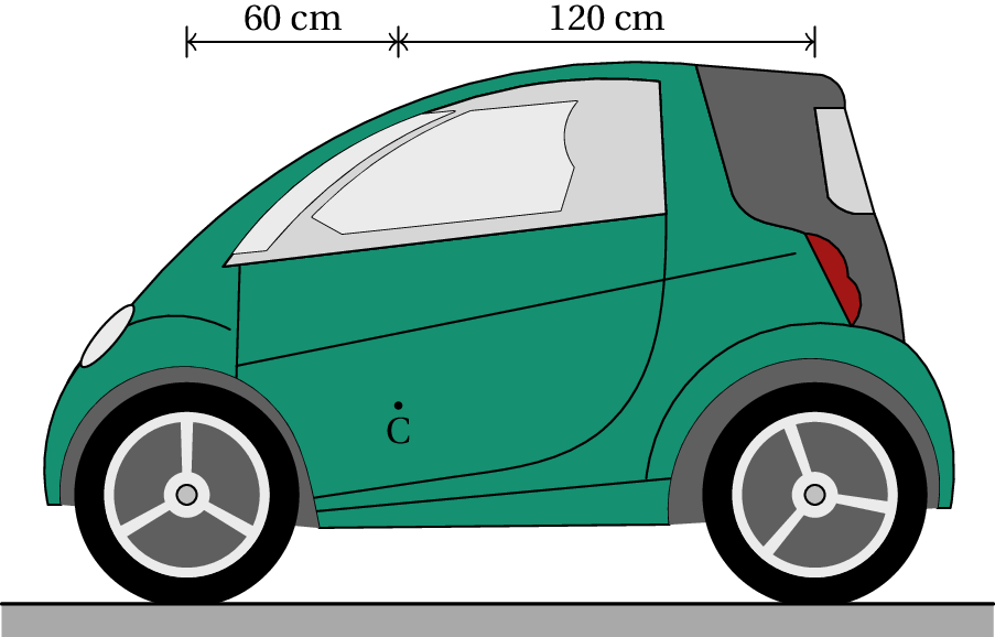
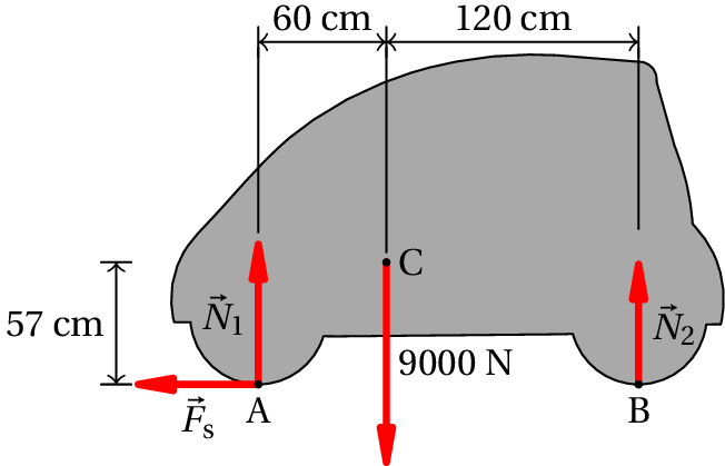
Example 5.1
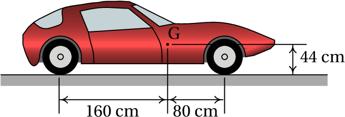
The car in the figure is stopped on a horizontal road. The car weighs
9000 N and its center of gravity, C, is 60 cm behind the front wheels
axle and 120 cm in front of the rear wheels axle. Find the normal
force on each tire.
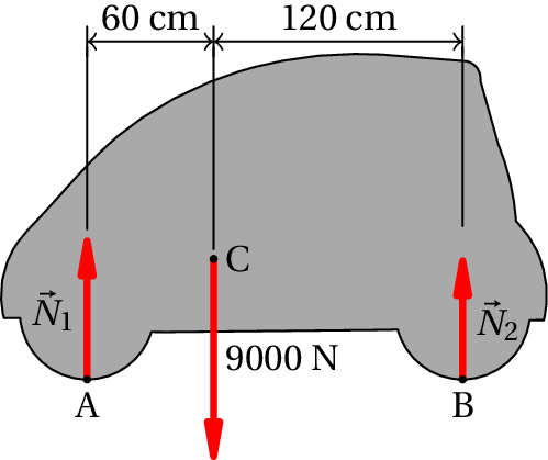
Resolution. The car is in equilibrium, since it is at rest. The
figure on the right shows the free-body diagram for the car;
is
the sum of the two normal forces on the front tires and
is the
sum of the normal forces on the rear tires. If there are frictional
forces in the tires, they can not be calculated when we consider the
whole car as a single rigid body; all we can conclude is that the sum
of the frictional forces in the four tires is zero. The condition for
the sum of the vertical forces to be zero is:
To find the value of these two variables, we must also use the
condition that the sum of the moments of all forces, about any chosen
point, must be zero. The sum of the moments about point A is:
This value could then be substituted in the condition for the sum of
the vertical forces, but it is also possible to use the condition that
the sum of moments about point B is also zero:
Assuming that the center of gravity is at the same distance from the
left and right tires, the normal forces on the two front tires would
be the same and therefore the normal force on each front tire would be
N. And in each rear tire the normal force would be
N.
If the car were moving with constant velocity, it would
still be in equilibrium but we would then have to take into
account the air resistance which is a force pointing to the
right and a little downwards. There would be frictional
forces in the tires, the sum of which would be equal and
opposite to the horizontal component of the resistance force
of the air. Since the frictional forces and the air
resistance force act on different lines of action, they
would produce a couple that would make the car rotate,
increasing the normal forces in the rear tires and
diminishing the normal forces in the front tires. To compute
that couple, it would be necessary to know the drag
coefficient
, the speed of the car and the
point of application of the resultant resistance force.
5.5. Center of mass
The mass in a rigid body is continuously distributed in a volume. If
the total mass of the body is
and
is the
infinitesimal mass that exists in the neighborhood of a point in the
body, then
(5.13)
Where the integral is a triple integral, within the volume occupied by
the solid, since
is the product of the density
times the infinitesimal volume
.
The position vector of the center of mass,
, is
defined as the mean value of the positions of the parts of the body,
weighed by their mass; namely,
(5.14)
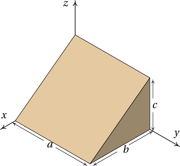
Example 5.2
Find the position of the center of mass of the homogeneous solid shown
in the figure.
Resolution. The volume of the solid is delimited by the 5
planes
,
,
,
and
.
The infinitesimal area
Is equal to the density
times the infinitesimal volume, which in cartesian coordinates is
. We begin by calculating the
total mass from equation 5.13:
Since the body is homogeneous,
is constant. In Maxima, the
three integrals must be calculated sequentially; the
variable p will represent the density
We conclude that the position vector of the center of mass is:
.
In every rigid body there is always a single point which is the center
of mass. If the origin is chosen exactly at the center of mass, the
integral in equation 5.14 will be zero
for each of the three components:
(5.15)
The integrals in 5.15 are all zero only
if the origin is at the center of mass.
Differentiating the two sides of
equation 5.14, with respect to time,
gives the expression of the velocity of the center of mass:
(5.16)
That is, the velocity of the center of mass is the average of the
velocities of all parts of the body, weighted by their masses.
And differentiating equation 5.16 with
respect to time we obtain the acceleration of the center of mass:
(5.17)
Which is the mass-weighted average of the accelerations of all the
parts of the body.
If the reference in which the accelerations
are measured is
an inertial reference frame, the product
is
equal to the total force
acting on the part with
mass
:
(5.18)
Notice that whenever a rigid body is accelerating, there must be an
infinitesimal force
applied to each part of the
body, making them all move together. In most points that force is due
solely to the internal forces of contact between the parts of the
body, forces that are triggered throughout the body by the action of
external forces
,
, …,
applied in
points: 1, 2, …,
, where the force
includes the contact forces plus a external force. The differential
gives the variation of the total force throughout
the body.
Substituting the expression 5.18
into equation 5.17, we conclude that,
(5.19)
In the integral on the left-hand side, for each internal contact force
that exists at one part, there will be another equal but opposite
force at another neighboring part, due to the law of action and
reaction. Therefore, all the internal forces of contact will be
eliminated and the integral will give the sum of the external forces,
,
,
,
, Which is the resultant
force on the rigid body. As such,
equation 5.19 leads to,
(5.20)
This important result is the law of motion for the translation of a
rigid body:
The motion of the center of mass of any rigid body with mass
is
equal to the motion that would have a point particle with mass
under the action of a force equal to the resultant force on the rigid
body.
Remember that the resultant force is obtained by adding all external
forces as if they were free vectors. If the resultant force is zero,
the center of mass will either be at rest or in a state of uniform
rectilinear motion, but other points on the rigid body may have more
complicated motions.
In the case of the weight, the external force is applied in all parts
of the rigid body and the resultant force is
. Hence,
equation 5.19 gives,
(5.21)
If the acceleration of gravity
is the same in all points of
the body, the integral on the left-hand side will be equal to
and we conclude that the acceleration of the center of
mass equals the acceleration of gravity and that
the center of
gravity, i.e. the point where the total weight acts, coincides
with the center of mass. For rigid bodies with size much smaller than
Earth, the acceleration of gravity can be considered constant
throughout the whole body and the center of mass is at the same point
as the center of gravity.
Let us consider for example a triangular piece of board. Hanging it by
one of the vertices, it will begin to oscillate until it stops in a
position where the center of gravity is in the same segment of
vertical line that passes through the vertex; by tracing this segment
in the triangle and repeating the procedure for the other two
vertices, the point where the three segments intersect will be the
center of gravity and center of mass. If the density of the triangle
is equal at all points, each of the vertical segments will be
the median that divides the
triangle into two parts with the same area and mass; therefore, the
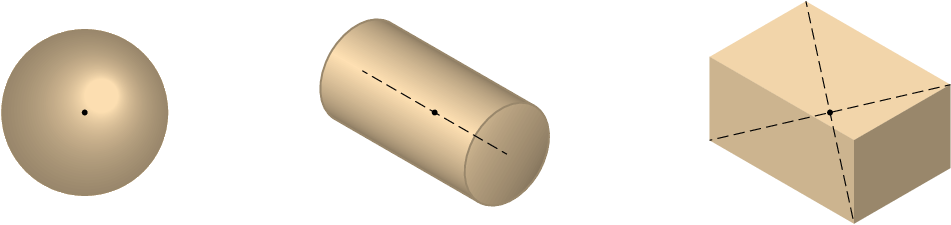
center of mass is at the intersection of the three medians. In bodies
with symmetrical shapes and constant density, the center of mass lies
in the geometric center. Figure 5.10 shows
three other examples.
Figure 5.10: Center of mass of 3 objects with constant density:
a sphere, a cylinder and a parallelepiped.
5.6. Translation without rotation
In a rigid body moving along any path without rotating, the
acceleration of all points is the same at every instant, equal to the
acceleration of the center of mass, which is equal to the resultant
force divided by the mass of the body. As the body does not rotate,
the resultant couple about the center of mass should be zero. It
should be noted that resultant couple is zero only about center of
mass and not about other points. The resultant couple about an
arbitrary point P, equals the couple of the resultant force, applied
at the center of mass.
Example 5.3
The same car of example 5.1, accelerates during
20 s, starting from rest and reaching a final speed of 60
km/h. Knowing that the center of gravity is 57 cm high above the
ground, and assuming that the acceleration is constant, determine the
normal forces and the frictional forces in the tires, at the instant
when it starts moving.
Resolution. When the car starts moving there is no air
resistance force, because its speed is zero. Therefore, the only
horizontal forces, responsible for the acceleration, are the static
frictional forces between the tires and the road. The following figure
shows the free-body diagram of the car.
is the sum of the two normal forces in the two front
tires,
is the sum of the normal forces in the rear tires
and
is the sum of the frictional forces in the
four tires. Since the tangential acceleration is constant, it is then
equal to increase of the velocity, divided by the time it took to
increase:
The law of motion for translation leads to the following equations:
Since the car is not rotating, the resultant couple about the center
of mass must be equal to zero. The weight does not produce any moment
about the the center of mass. The moments of
and
about the center of mass are in the clockwise
direction and the moment of
about the center of mass is in
the counterclockwise direction. The resultant couple about the center
of mass is then:
The solution of that system of the 3 equations is,
The total frictional forces in the four wheels is 765 N, the
normal force on each front tire is 2879 N and the normal force
on each back tire is 1621 N. Notice that in the free-body
diagram it makes no difference to put the frictional force in the
front wheels or the back wheels; but since it is a traction force, it
will really be produced on the wheels where the traction of the car is
(wheels made to rotate by the engine).
5.7. General motion of the rigid body
The dynamics of the rigid body consists of the study of the effects of
external forces and couples on the variation of its six degrees of
freedom. The trajectory of any point in the body, used as reference
point, gives the variation of three of these degrees of freedom. The
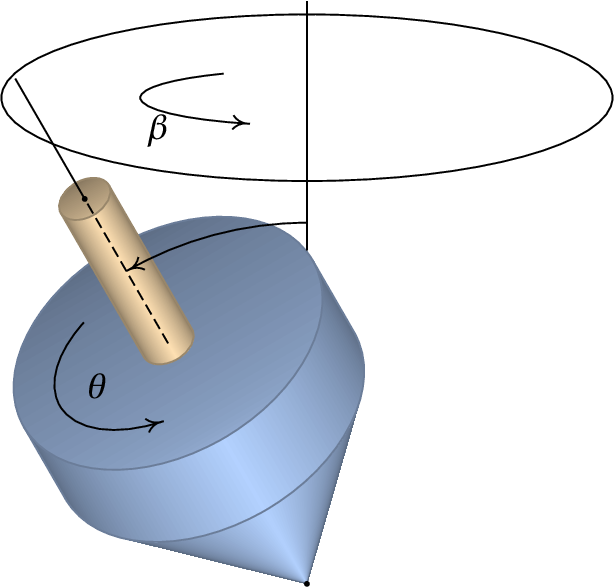
remaining 3 degrees of freedom are 3 angles. In the spinning top shown
in figure 5.11, the two angles
and
define the direction of the axis of the top; a third angle,
, is related to the rotation of the top with respect to its
axis. In this case two of the angles,
and
, vary with
time and therefore, there are two angular velocities
and
.
Figure 5.11: The 3 degrees of freedom in the rotation of a
rigid body.
The top is spinning around its axis in the direction indicated in the
figure for the angle
, with angular velocity
. Therefore, its angular velocity vector,
, is in the direction of its axis and from the ground to
the upper part. Since the axis of the spinning top is not in a
vertical position, its weight and the normal force on the tip of the
top produce a couple in the direction in which
increases. That
couple produces angular acceleration
tangent to the
circumference shown in the figure in the direction shown for the angle
, which makes the angular velocity vector
rotate
with angular velocity
along the circumference.
The general motion of a rigid body is easier to study using lagrangian
dynamics, instead of the vector dynamics used in this chapter. We will
conclude the chapter considering a simpler case in which the axis of
rotation does not move, so there is only one angle changing with time.
5.8. Rotation with fixed axis
When the axis of rotation of a rigid body remains fixed relative to an
inertial frame, Newton's second law will be valid for the
accelerations measured in the frame of the rigid body. Thus,
equation 3.35 allows us
to calculate the force acting on each part with differential mass
(5.22)
Each of these forces produces a moment
about the origin, but
since the rigid body can only rotate around the fixed axis
, it is only relevant to compute the
component of
the moment, obtained using only the projection of the position vector
on the rotation plane:
(5.23)
By integrating in the volume of the rigid body the
component of
the resulting moment is then,
(5.24)
The angular acceleration was placed outside the integral, because it
is the same at all points of the rigid body. The integral on the
right-hand side,
(5.25)
Is called moment of
inertia of the rigid body, relative to the
axis.
In the integral
, all moments of the internal
forces of contact will cancel, as a consequence of the law of action
and reaction, and the result will be resultant couple of the external
forces,
,
, …,
. Thus,
equation 5.24 leads to the law of
motion for rigid body rotation around a fixed axis:
(5.26)
In a rigid body that can only rotate around a fixed axis, the
resultant couple with respect to a point in the axis has component
along that axis equal the product of the body's moment of inertia
relative to the axis, times the angular acceleration.
Example 5.4
Determine the moment of inertia of a homogeneous cylinder of radius
and height
, around its axis.
Resolution. It is convenient to use cylindrical coordinates
with the
axis at the axis of the cylinder. The volume of the
cylinder is defined by the conditions:
,
,
(we use
for the
cylindrical coordinate, to avoid confusion with the cylinder radius).
The differential element of volume in cylindrical coordinates is
(
) and hence,
,
where
is the density. The moment of inertia is then,
Notice that the mass of the cylinder is obtained by the integral:
Thus, the expression for the moment of inertia is:
The role played by the moment of inertia in rotations is similar to
the role of the mass in translation motions. The bigger the moment of
inertia, the less the angular acceleration that the resultant couple
will produce. Observe the similarity between
equation 5.26 and Newton's second law.
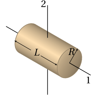
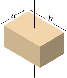
Table 5.1 shows the expressions of the
moment of inertia of some solids around the axes that pass through
their center of mass. The moment of inertia is always directly
proportional to the mass of the body. The radius of gyration is
a typical length for each geometrical shape, defined as the square
root of the moment of inertia divided by the mass:
(5.27)
Table 5.1: Moments of inertia of some solids with constant
density around axes passing through the center of mass.
Sphere
Cylinder
Parallelepiped
Axis 1:
Axis 2:
The moment of inertia around an axis through the center of mass can be
used to obtain the moment of inertia around any other parallel axis
out of the center of mass, using
the parallel-axis theorem :
(5.28)
where
is the mass of the body and
is the distance
between the two parallel axes. It is also possible to
compute the moment of inertia of a body by adding the
moments of inertia of the various parts of it, since the
integral 5.25 can be written
as the sum of the integrals in the various parts.
The moment of a thin bar of length
can be obtained from
table 5.1, either for the expression for
a cylinder, around axis 1 and in the limit
, or from
the expression for a parallelepiped with
and
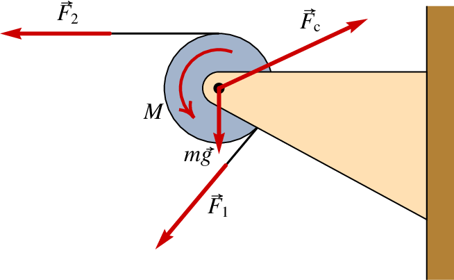
A pulley with a shaft attached to a fixed base is an example of a
rigid body with a fixed rotation axis. If the pulley is homogeneous,
the center of mass will also be on the axis of the
shaft. Figure 5.12 shows a pulley of
mass
and radius
, with a string that moves with the pulley
without sliding on its surface. The external forces and couples are
the weight,
, the tensions in the string in both sides of
the pulley,
and
, the contact force on the
shaft,
and a couple
produced by friction
between the shaft and the pulley, in the direction opposite to the
rotation of the pulley (the pulley was assumed rotating clockwise in
figure 5.12).
Figure 5.12: External forces and couples on a pulley.
The weight of the pulley and the contact force
do not produce moment around the
axis. Since the pulley is a cylinder, using the expression
for the moment of inertia in
table 5.1, the equation for
the resultant couple is (assuming the angular acceleration
is in the clockwise sense),
(5.29)
When friction on the shaft can be ignored,
(5.30)
where
is the tangential acceleration of a
point on the string. Note that, regardless of the radius of the
pulley, when its mass is much smaller than
and
, it may be assumed that the tension is equal on
both sides of the rope.
Questions
(To check your answer, click on it.)
The cartesian components of a force are
. In which of the positions
on the list should the force be applied to produce a clockwise moment
about the origin?
Two children with masses 30 kg and 45 kg are sitting on
both sides of a seesaw. If the heavier child is sitting 1.2 m from the
pivot point of the seesaw, how far from that point should the other
child sit to keep the seesaw balanced?
1.5 m
0.8 m
1.8 m
1.2 m
0.98 m
If an object is divided into two parts, making a vertical cut along a
line that passes through its center of gravity, which of the
statements about the two pieces obtained is true?
They must have the same mass.
They may have different masses.
They should have the same weight.
They must have the same area.
They must have the same volume.
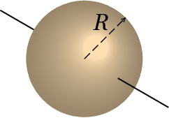
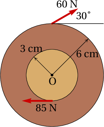
Two external forces are exerted on a wheel, as shown in the
figure. Compute the resultant moment about point O, in units of N·m.
0.57
1.05
4.35
5.67
6.15
A metal part with constant density and mass
is constructed with
two cylinders of the same height, but two different radii
,
glued one over the other so that their axes are aligned. Find the
expression of the moment of inertia of the part around its axis of
symmetry.
Problems
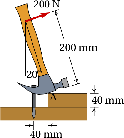
The hammer in the figure is placed over a block of wood of 40 mm of
thickness, to facilitate the extraction of the nail. If a force of 200
N (perpendicular to the hammer) is required to extract the nail, find
the force on the nail and the force at point A while the nail starts
to be removed in the position shown. Assume that the weight of the
hammer can be neglected, compared to the other forces and that there
is enough friction in A to prevent the hammer from sliding.
A front-wheel drive car accelerates evenly from rest reaching a speed
of 100 km/h in 11 seconds. If the car's weight is 9750 N, find the
normal reactions and the frictional force on each tire, in the moment
when it starts moving. What is the minimum value that should have the
coefficient of static friction between the tires and the road so that
the car can achieve this acceleration?
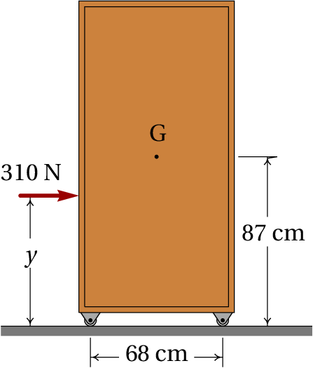
A 45 kg cabinet, mounted on wheels that let it roll freely on the
floor, is accelerated by an external force of 310 N.
(a) Find the maximum and minimum values that the height
can
have for the cabinet to accelerate without the wheels losing contact
with the ground.
(b) Find the cabinet's acceleration when
is between the
minimum and maximum values obtained in part a.
Using integration in the volume of the solid, prove the result of
table 5.1 for the moment of inertia of a
rectangular parallelepiped with axis of rotation perpendicular to one
of its faces and passing through the center of mass.
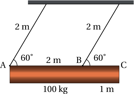
A homogeneous cylindrical wooden beam, with diameter of 48 cm, length
of 3 m and mass of 100 kg, is hung horizontally by means of two 2 m
ropes, as shown in the figure. The beam is released from rest in the
position where each rope makes an angle of 60° with the
horizontal. Determine the tension and angular acceleration of each
rope at the exact moment the beam is released from rest.
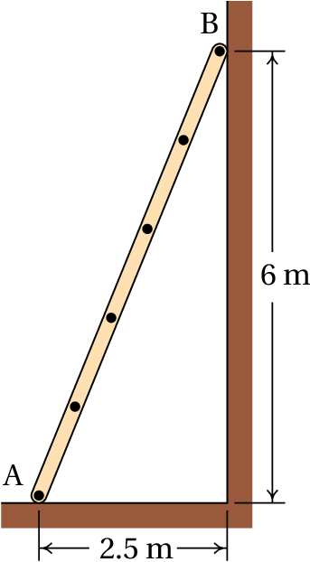
The ladder in the figure rests on a horizontal surface (point A) and a
vertical wall (point B). The coefficient of static friction between
the ladder and the horizontal surface is
, while the
friction of the ladder with the vertical wall is negligible. Assuming
that the center of gravity of the ladder is at half its length,
determine the minimum value of
, to ensure that the
ladder remains at rest.
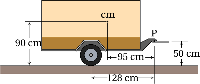
The mass of the trailer in the figure is 750 kg and is being hitched
by a car linked to the trailer at point P. The road is horizontal and
the two identical tires can be considered as one, with a single normal
reaction and negligible frictional force; the air resistance will also
be neglected. (a) Compute the normal force in the tires and the
vertical force at point P, when the speed is constant. (b) When
the car is accelerating, with
m/s2,
the force at P will have horizontal and vertical components. Compute
these components and the normal force in the tires (the moment of
inertia of the wheels and the friction with the road are negligible).
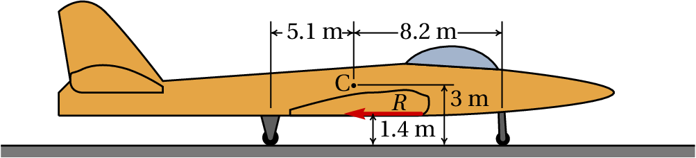
The airplane in the figure, with a total mass of
kg, lands on a horizontal track. Point C represents the
center of gravity. At the instant the speed is 210 km/h (to the
right), the pilot turns the turbines in reverse mode, producing the
constant force
shown in the figure, and after 580 m on the track
the speed decreases to 70 km/h. During that motion, the frictional
forces in the tires and the air resistance can be neglected, compared
to
which is much higher. Compute the normal force on the front
wheel.
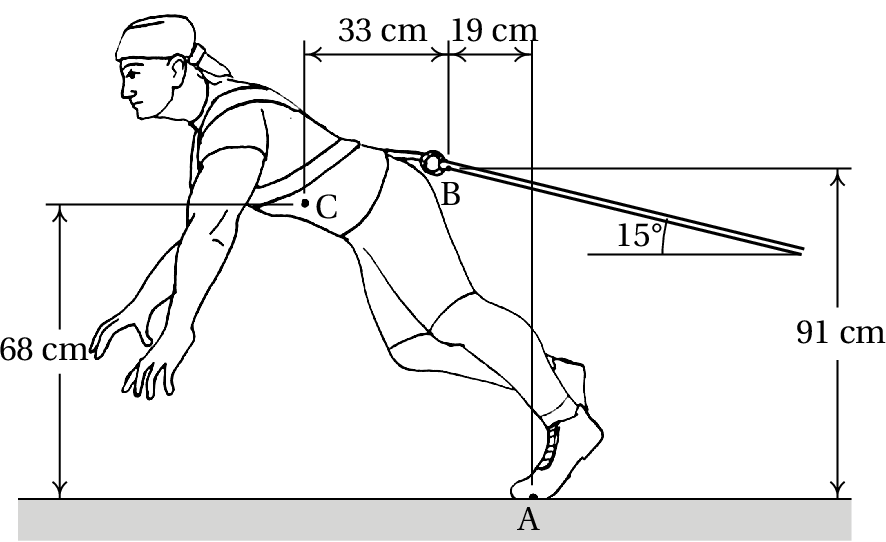
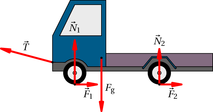
A 91 kg man pulls a truck on a horizontal road, with constant speed,
using a rope tied to his back. The figure shows the relative positions
of the center of gravity of the man, C, the point of contact of his
foot with the ground, A, and of the point where the rope is attached
to his back, B.
(a) Compute the magnitude of the tension on the
rope. (b) Draw a diagram of the forces you think might be
acting on the truck.
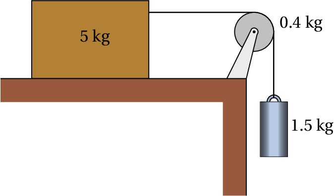
The 1.5 kg cylinder in the figure descends vertically, causing the 5
kg block to accelerate on the horizontal table. The pulley can be
considered a uniform disk with mass of 0.4 kg. The string rotates with
the pulley without sliding on its surface. The coefficient of kinetic
friction between the block and the table is 0.2. Determine the value
of the acceleration of the block and cylinder, neglecting the friction
in the pulley's shaft, the mass of the string and the resistance of
the air.
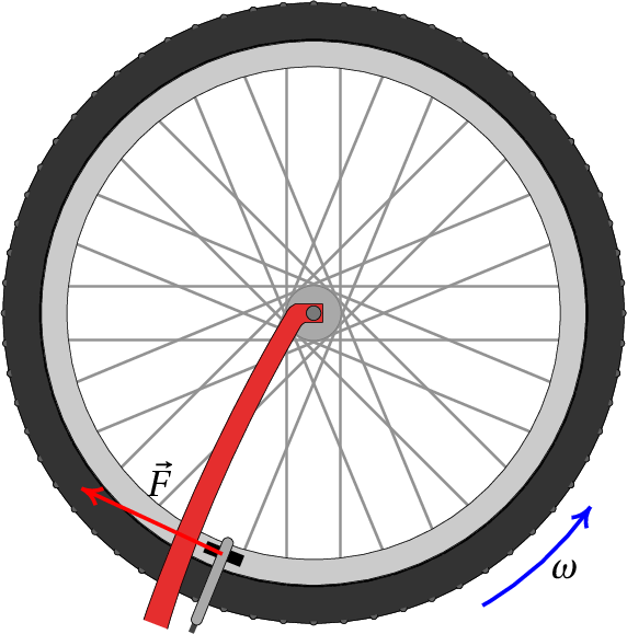
To test its brakes, a bicycle was placed with the wheels in the air
and the front wheel was made to rotate freely, as shown in the
figure. The time taken for the wheel to make 10 turns was measured
giving 8.2 s (assume that during those 8.2 s the angular velocity
remained constant). Immediately afterwards, the brakes were
applied and the wheel took 2.9 s until it stopped completely. The
figure shows the frictional force
between the friction pads
and the rim, which is tangent to the rim and applied at a distance of
27.1 cm from the wheel axis.
(a) Assuming that the force
is constant, the angular
acceleration it produces will also be constant; compute the angular
acceleration.
(b) Determine how may turns the wheel rotated from the moment
the brakes were applied until it stopped.
(c) Knowing that the moment of inertia of the wheel around its
axis is 0.135 kg·m2, find the magnitude of the force
.
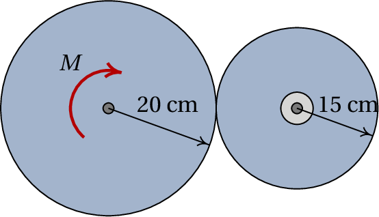
A wheel A, with radius of 20 cm, mass of 600 g and a radius of
gyration of 12 cm (relative to its axis), is connected to a motor that
exerts a couple
N·m on it, in the direction shown in
the figure. Wheel B, with radius of 15 cm, mass of 400 g and radius of
gyration of 10 cm (relative to its axis) remains in contact with wheel
A, without slipping. Wheel B is attached to its shaft by means of a
bearing, which causes the friction in the shaft to be
negligible. Determine the angular acceleration of wheel
B. Hint: analyze the free-body diagrams of the two wheels,
keeping in mind that there is frictional force between them.
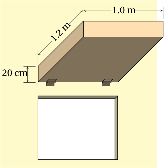
The homogeneous rectangular box in the figure is attached to two
hinges that let it turn covering the window, or move to the horizontal
position shown in the figure, to provide shade during the day. The
chain that holds the box in the horizontal position suddenly breaks
and the box falls hitting the wall. Determine the angular velocity
with which the box hits the wall, neglecting the friction in the
hinges and the air resistance.
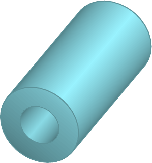
A cylindrical object
has mass
distributed uniformly between
and
(with
), with a cylindrical orifice of radius
, as shown in
the figure. Find the expression of the moment of inertia around the
axis of the cylinder. Hint: Determine the mass of the complete
cylinder, without orifice, in terms of
, and the mass of the
cylinder which is removed when the orifice is made; the moment of
inertia is equal to the moment of inertia of the complete cylinder
(see table 5.1 ), plus the moment of inertia of
the cylinder that has been removed, assuming that the mass of the
latter is negative!
To measure the moment of inertia of a pulley with 5 cm of radius, one
end of a string was glued to it, then rolled around it and the other
end was connected to a cylinder of mass
kg. The
cylinder descends freely unrolling the string and making the pulley
accelerate with angular acceleration
Rad/s2. Knowing that the friction in the
pulley shaft produces a constant couple
N·m, in the
direction indicated in the figure, find the moment of inertia of the
pulley around its axis.
Answers
Questions: 1. E. 2. C. 3. B.
4. D. 5. C.
Problems
The nail exerts a downward force of 1000 N.
(N)
Front Tires:
N,
N.
Rear tires:
N,
(Assuming the rear wheels are perfectly free). The minimum
coefficient of static friction is 0.416.
(a) Minimum height 38.6 cm, maximum height 135.4 cm
(b)
(m/s2)
In this case
and the volume of the solid
is defined by
,
,
.
N,
N,
Rad/s2
0.21
(a)
N,
N. (b)
N,
N,
N.
N.
(a) 559 N. (b) The forces acting in the truck are the
tension of the rope,
, the weight,
, the
normal forces in the tires,
and
and the
frictional forces on the tires,
and
:

 The hammer in the figure is placed over a block of wood of 40 mm of
thickness, to facilitate the extraction of the nail. If a force of 200
N (perpendicular to the hammer) is required to extract the nail, find
the force on the nail and the force at point A while the nail starts
to be removed in the position shown. Assume that the weight of the
hammer can be neglected, compared to the other forces and that there
is enough friction in A to prevent the hammer from sliding.
The hammer in the figure is placed over a block of wood of 40 mm of
thickness, to facilitate the extraction of the nail. If a force of 200
N (perpendicular to the hammer) is required to extract the nail, find
the force on the nail and the force at point A while the nail starts
to be removed in the position shown. Assume that the weight of the
hammer can be neglected, compared to the other forces and that there
is enough friction in A to prevent the hammer from sliding.
 A 45 kg cabinet, mounted on wheels that let it roll freely on the
floor, is accelerated by an external force of 310 N.
A 45 kg cabinet, mounted on wheels that let it roll freely on the
floor, is accelerated by an external force of 310 N.
 The ladder in the figure rests on a horizontal surface (point A) and a
vertical wall (point B). The coefficient of static friction between
the ladder and the horizontal surface is
, while the
friction of the ladder with the vertical wall is negligible. Assuming
that the center of gravity of the ladder is at half its length,
determine the minimum value of
, to ensure that the
ladder remains at rest.
The ladder in the figure rests on a horizontal surface (point A) and a
vertical wall (point B). The coefficient of static friction between
the ladder and the horizontal surface is
, while the
friction of the ladder with the vertical wall is negligible. Assuming
that the center of gravity of the ladder is at half its length,
determine the minimum value of
, to ensure that the
ladder remains at rest.
 A cylindrical object
has mass
distributed uniformly between
and
(with
), with a cylindrical orifice of radius
, as shown in
the figure. Find the expression of the moment of inertia around the
axis of the cylinder. Hint: Determine the mass of the complete
cylinder, without orifice, in terms of
, and the mass of the
cylinder which is removed when the orifice is made; the moment of
inertia is equal to the moment of inertia of the complete cylinder
(see
A cylindrical object
has mass
distributed uniformly between
and
(with
), with a cylindrical orifice of radius
, as shown in
the figure. Find the expression of the moment of inertia around the
axis of the cylinder. Hint: Determine the mass of the complete
cylinder, without orifice, in terms of
, and the mass of the
cylinder which is removed when the orifice is made; the moment of
inertia is equal to the moment of inertia of the complete cylinder
(see 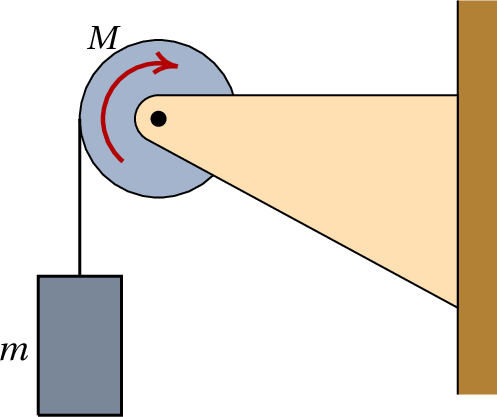
(Click to continue)